heh, implying anything short of thermite can truly fix a printer
no comment required on this blessed day
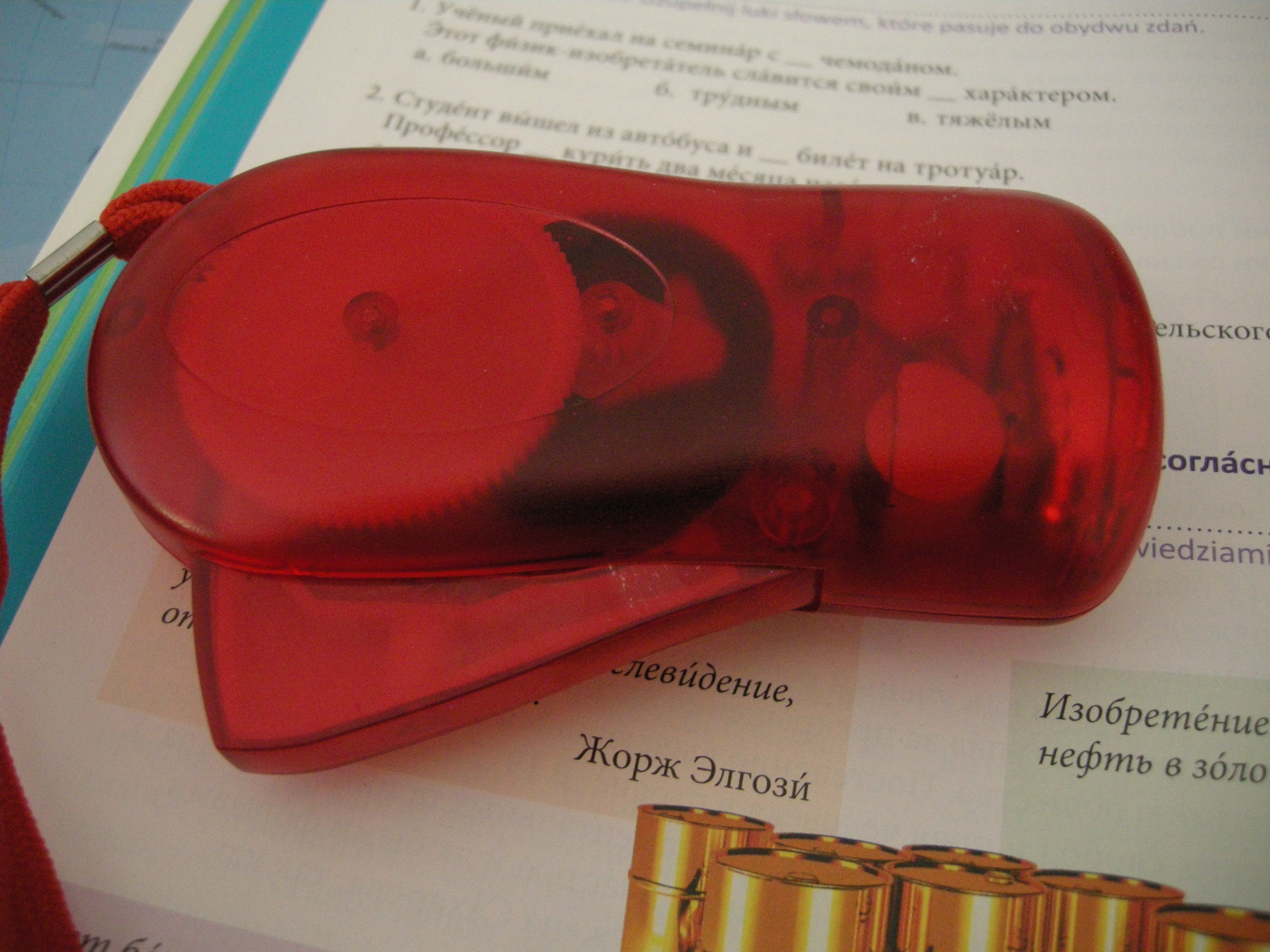
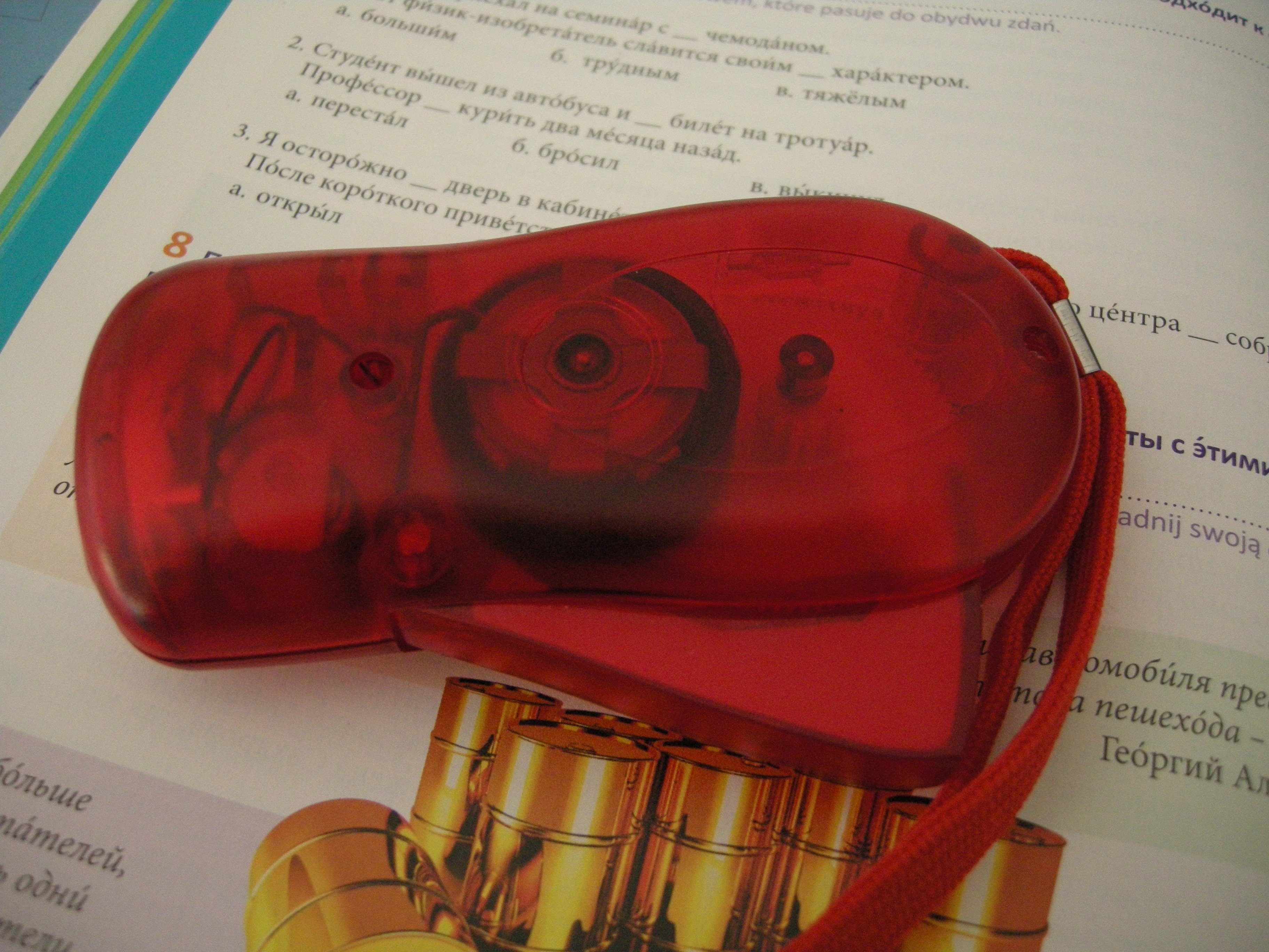
I'm supposed to be doing my Russian homework so let's take apart one of these reciprocating-crank-LED-lamps things for the equivalent of one buck
Replying to @nabijaczleweli
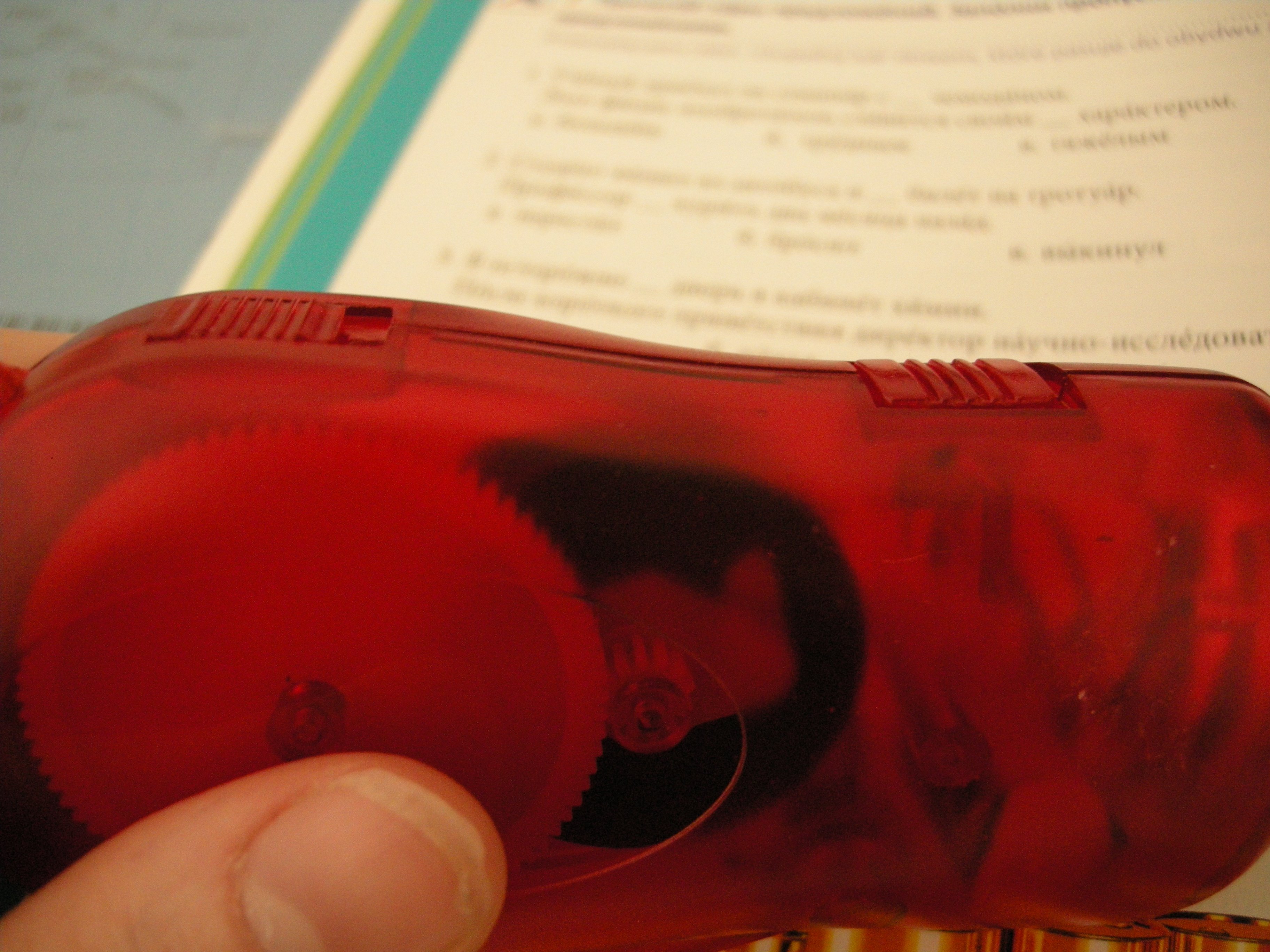
Right off the bat: two switch interfaces on the side, the one further forward toggles battery output, other one unused.
Replying to @nabijaczleweli
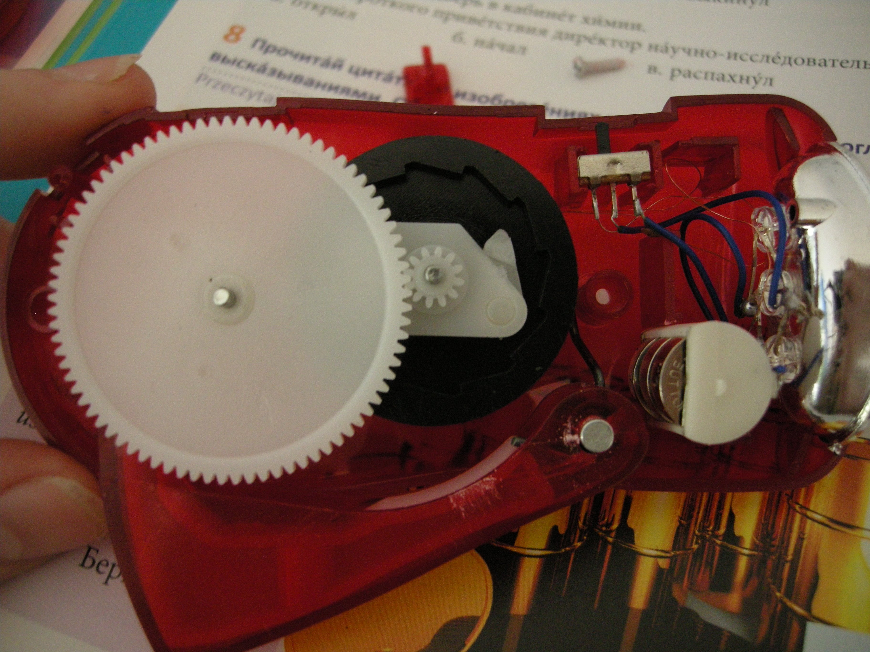
Two sides of the cover no longer held together by PH1 screws, revealing the juicy flesh.
Replying to @nabijaczleweli
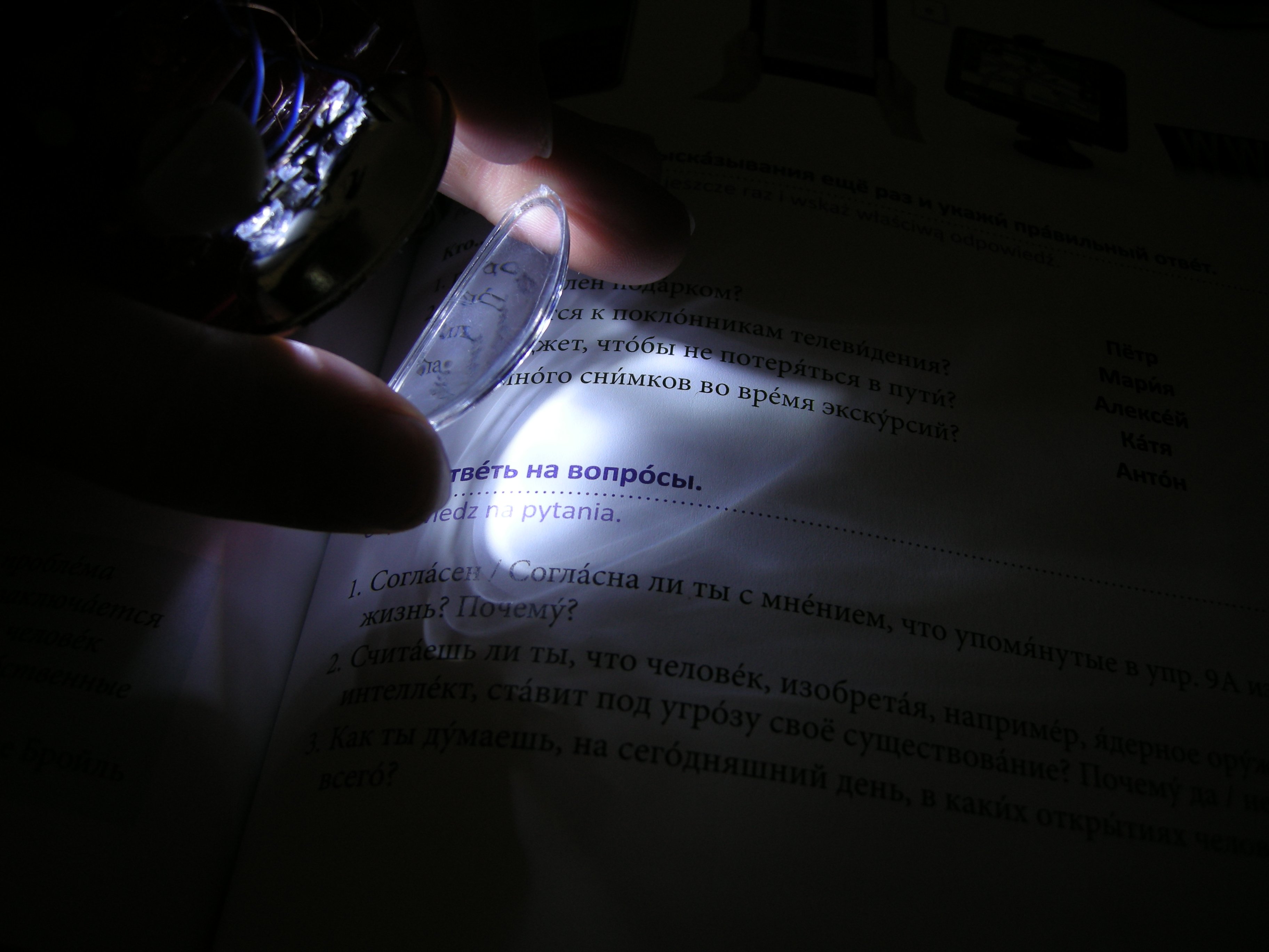
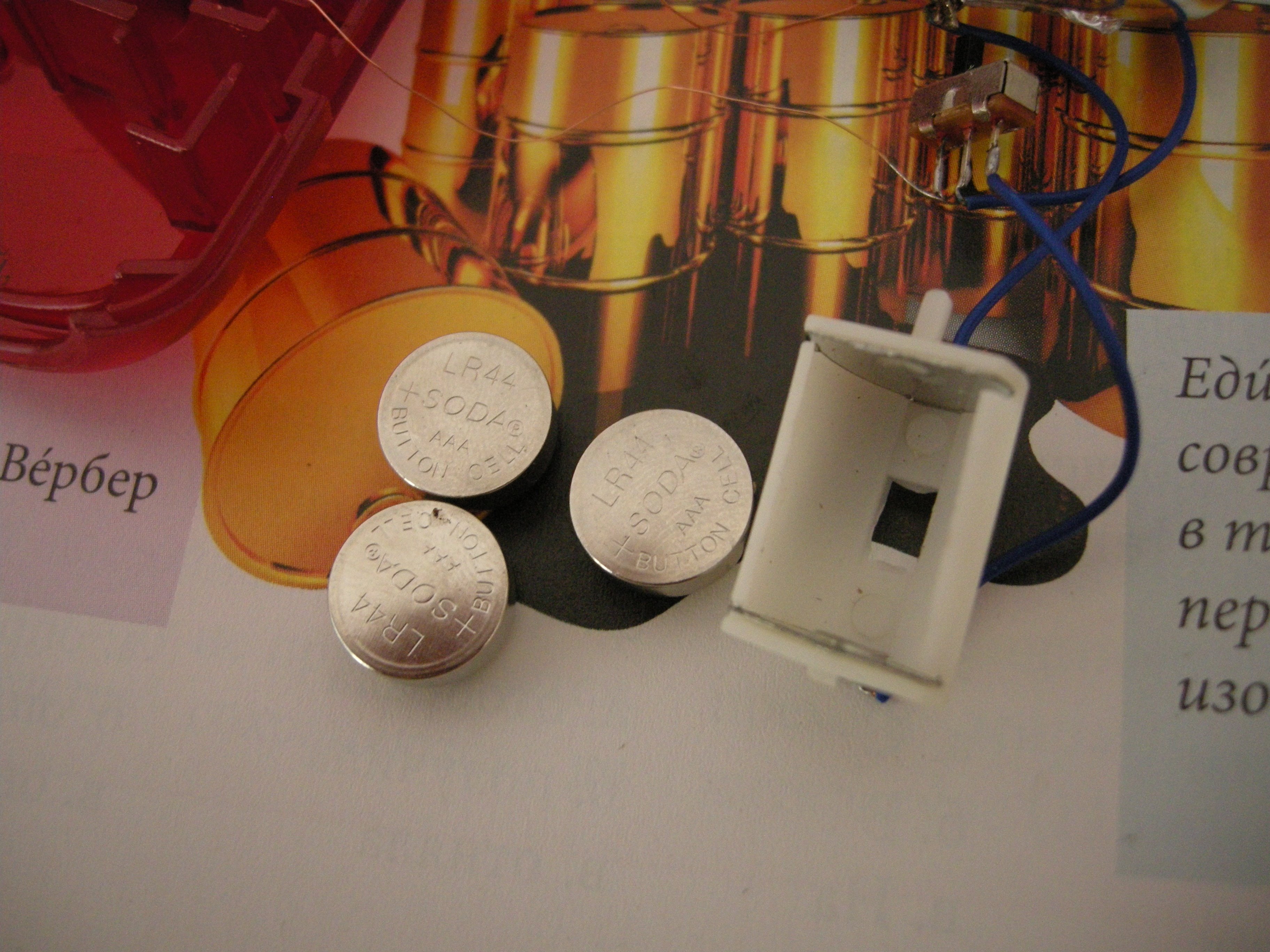
Trash lens comparison, battery source

Replying to @nabijaczleweli
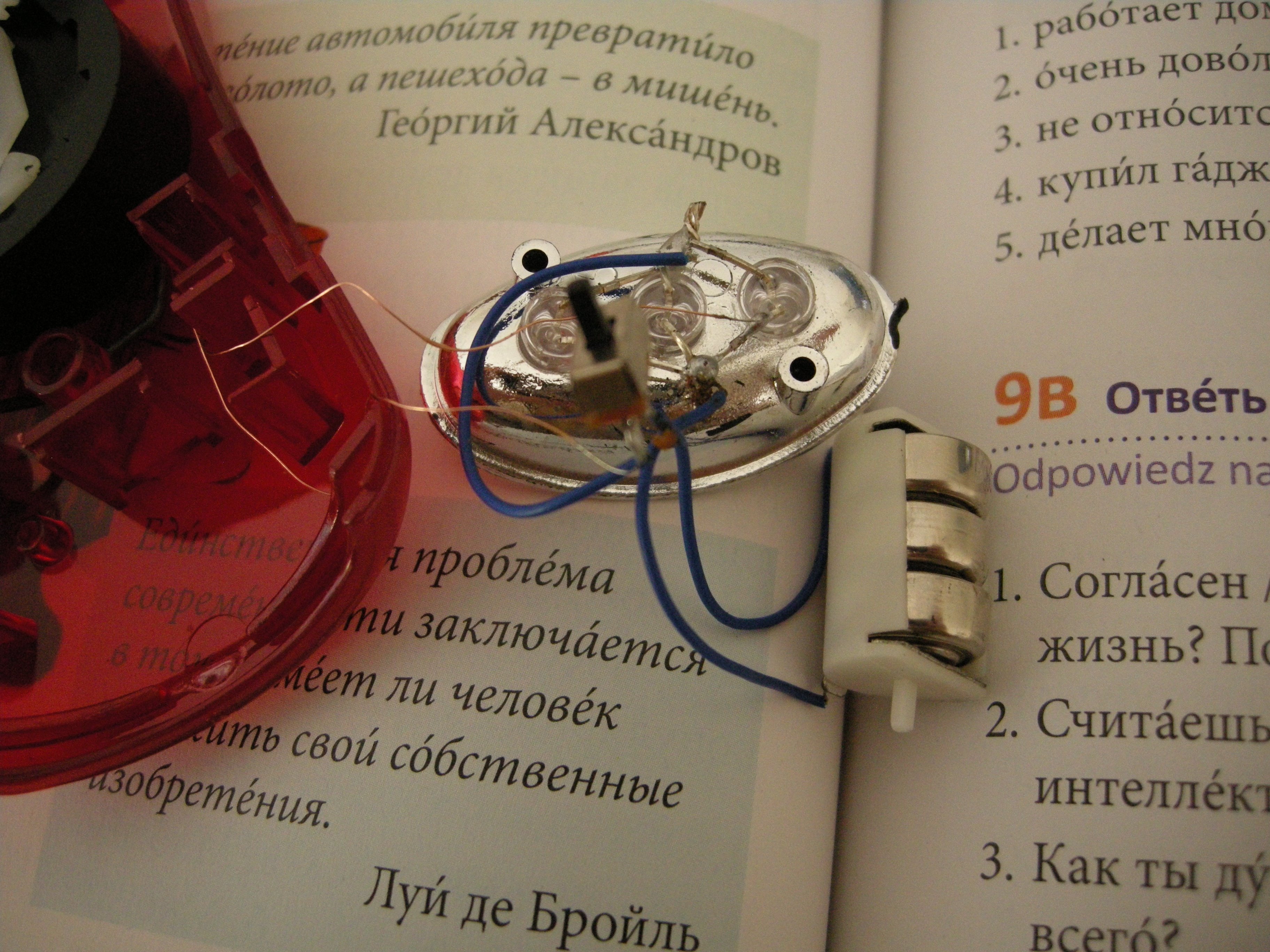
Triple-parallel LED assembly, 1P2T switch, common Bat+, no external resistor
Replying to @nabijaczleweli
Three LR44 cells, and the holder, which was quite smart actually, gotta give it that
Replying to @nabijaczleweli
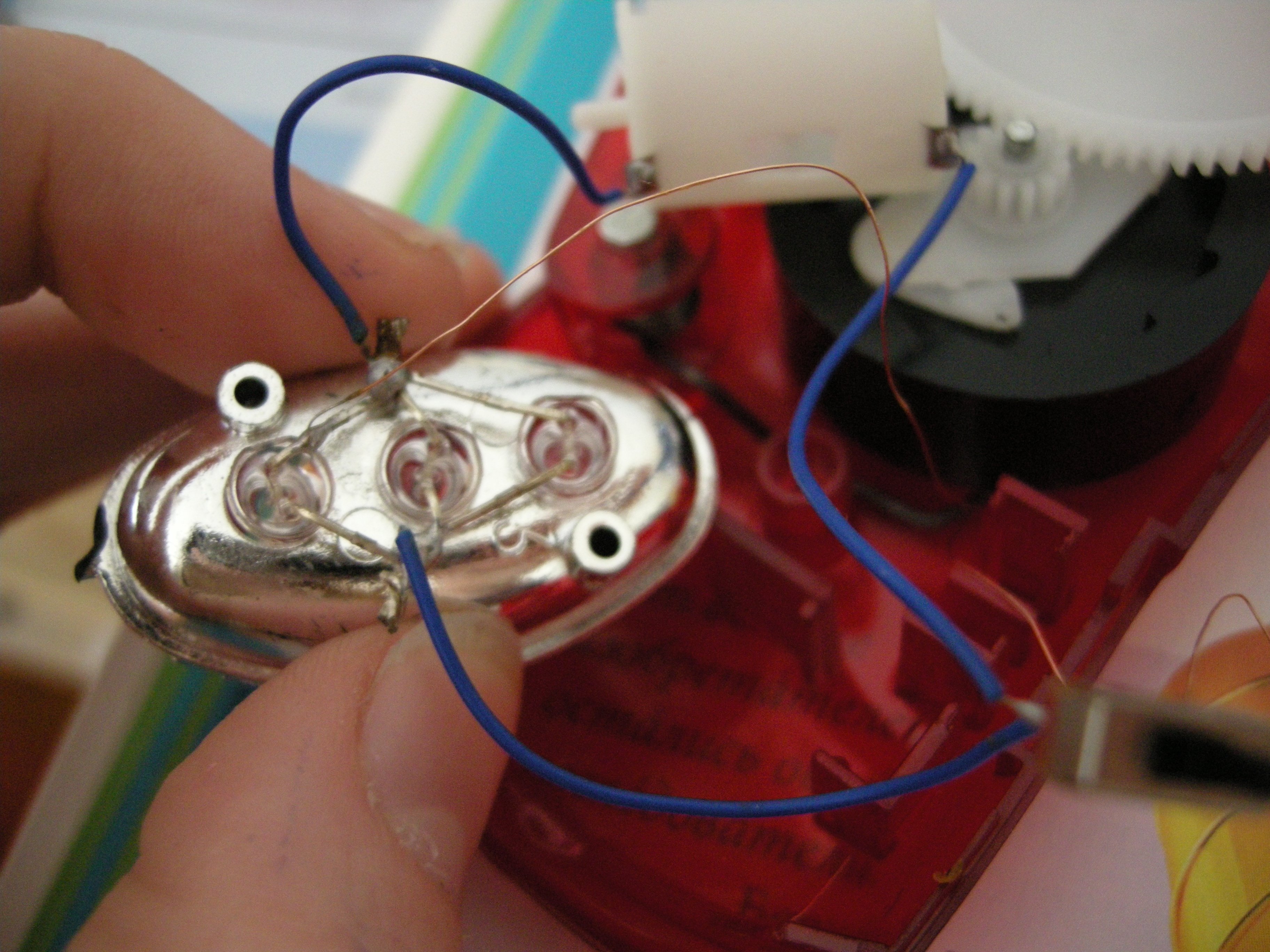
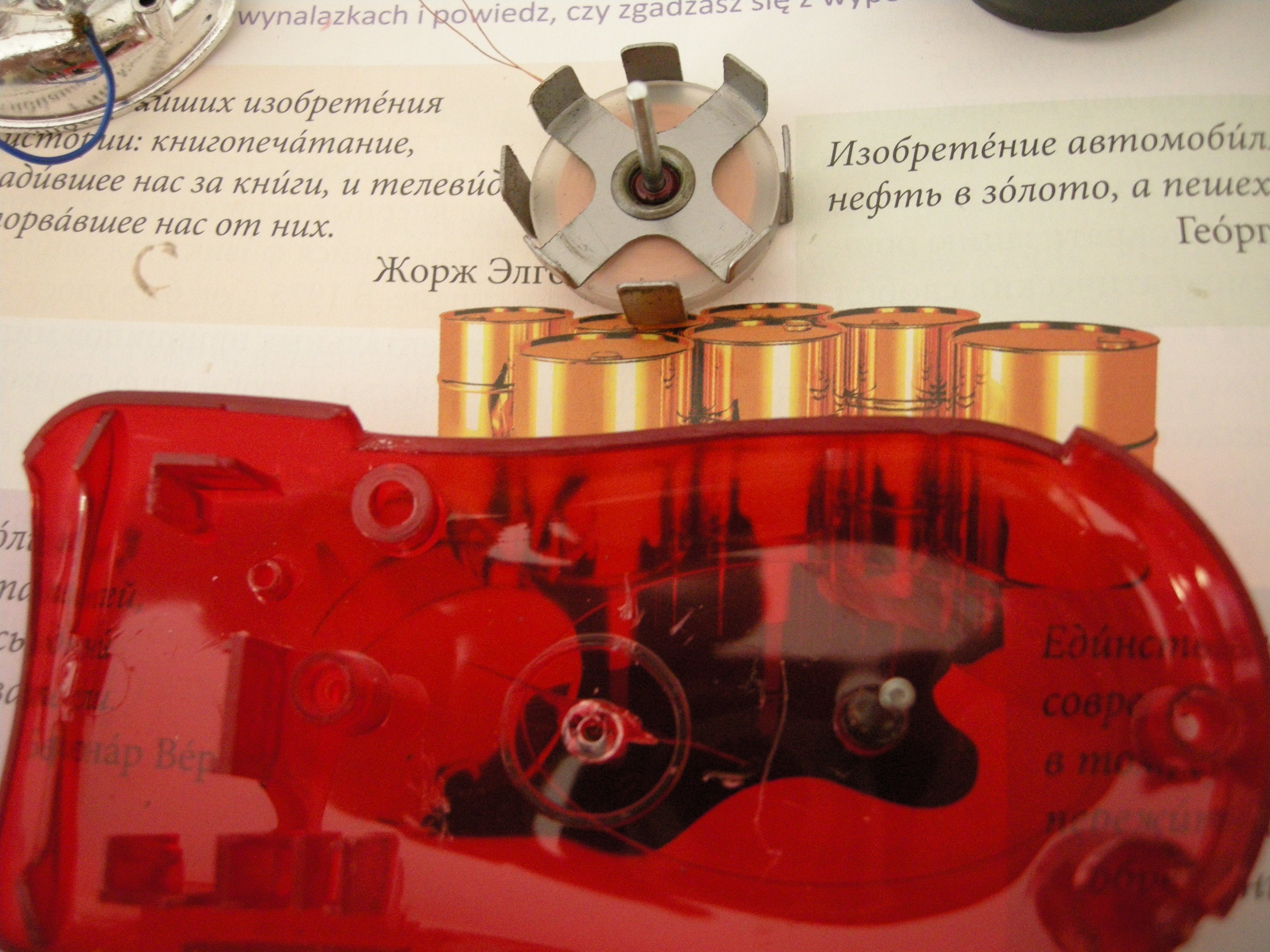
Close-up of the triple-parallel LED assembly, the two strands coming from under the spinny stack look suspiciously like magnet wire
Replying to @nabijaczleweli
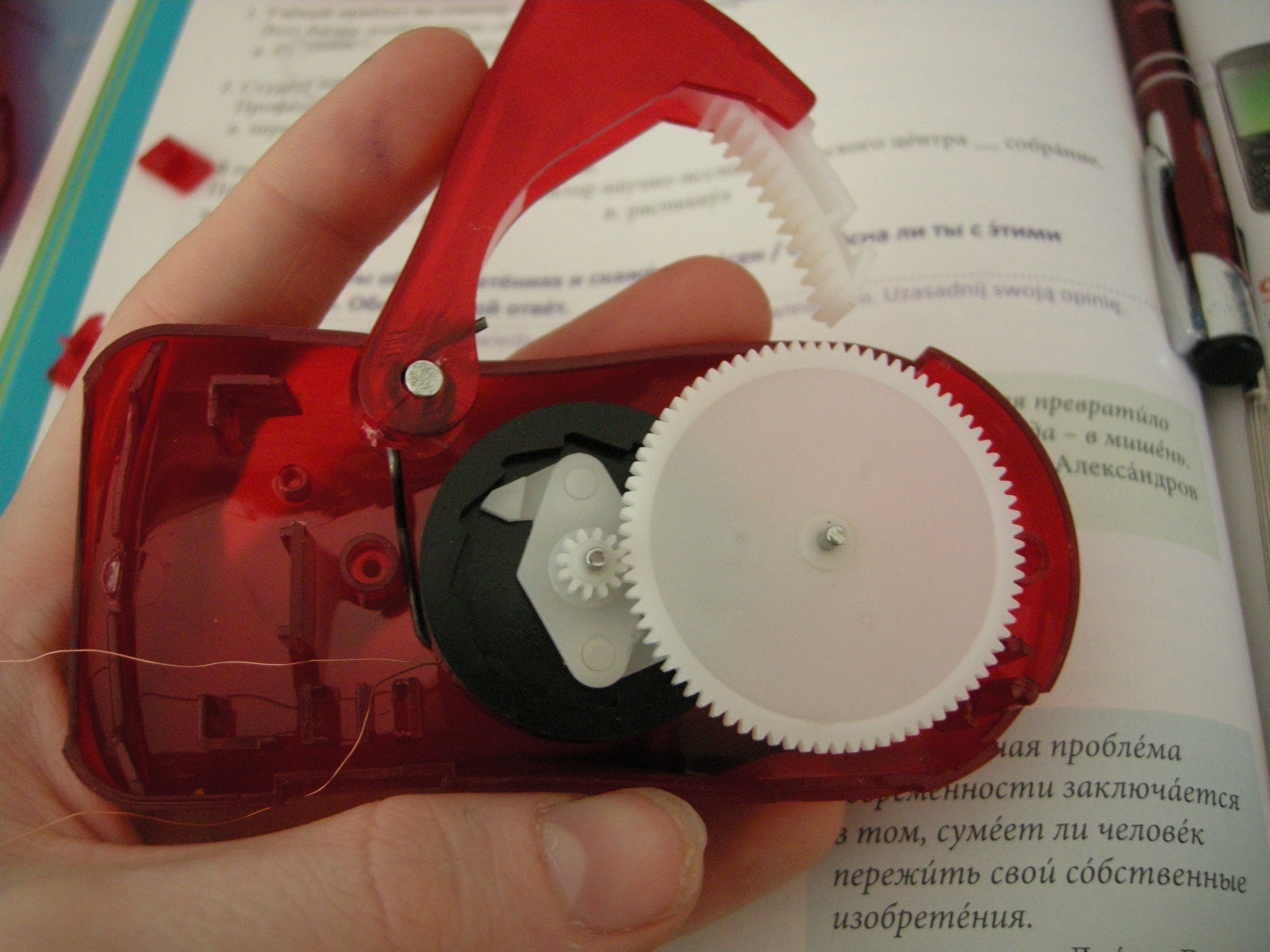
The crank action (neutral, full-in, extracted)
Replying to @nabijaczleweli
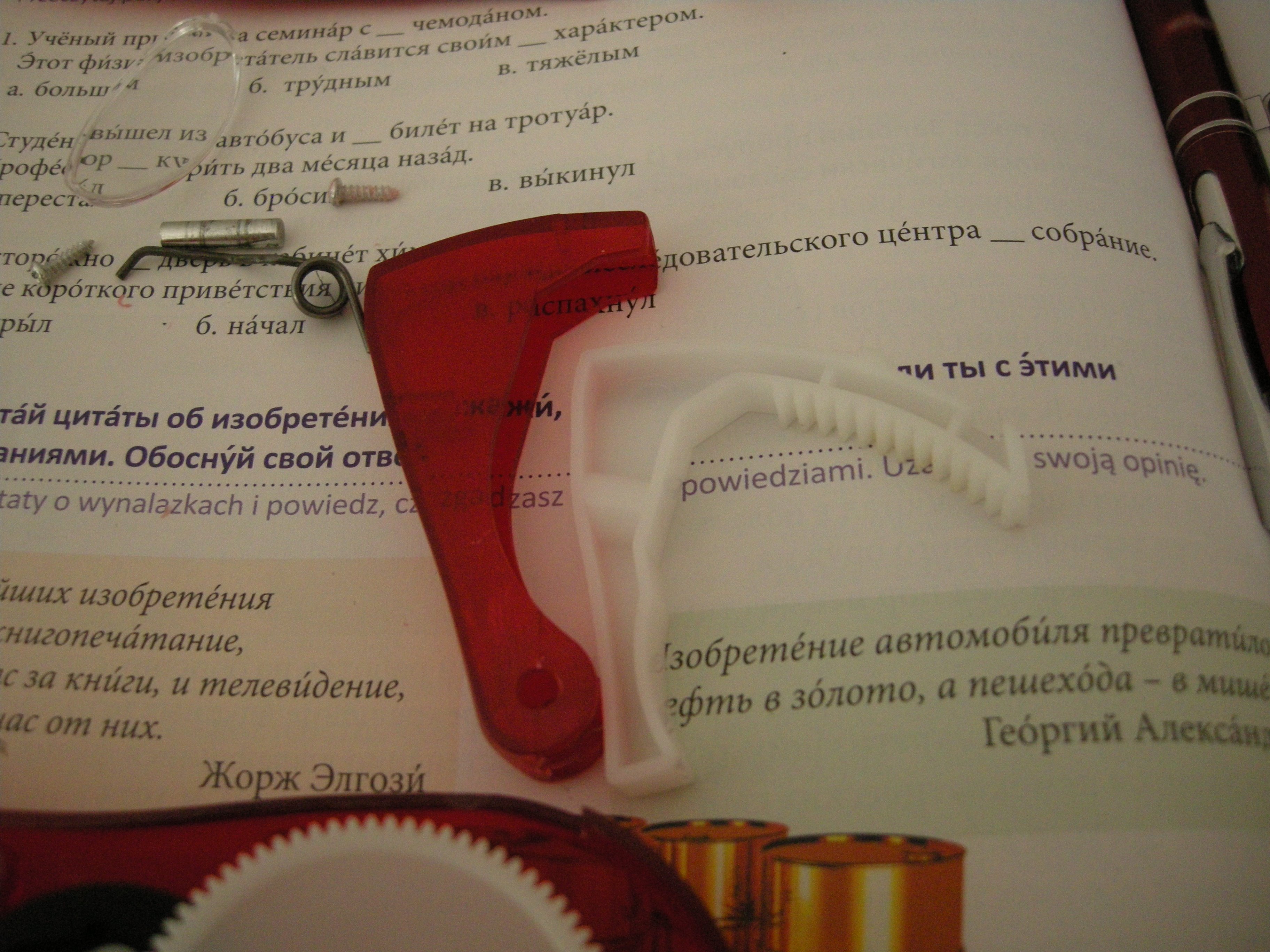
Crank handle held in by steel pin, spring reset action provided by, well, spring. All white plastics feel like a nylon.
Replying to @nabijaczleweli
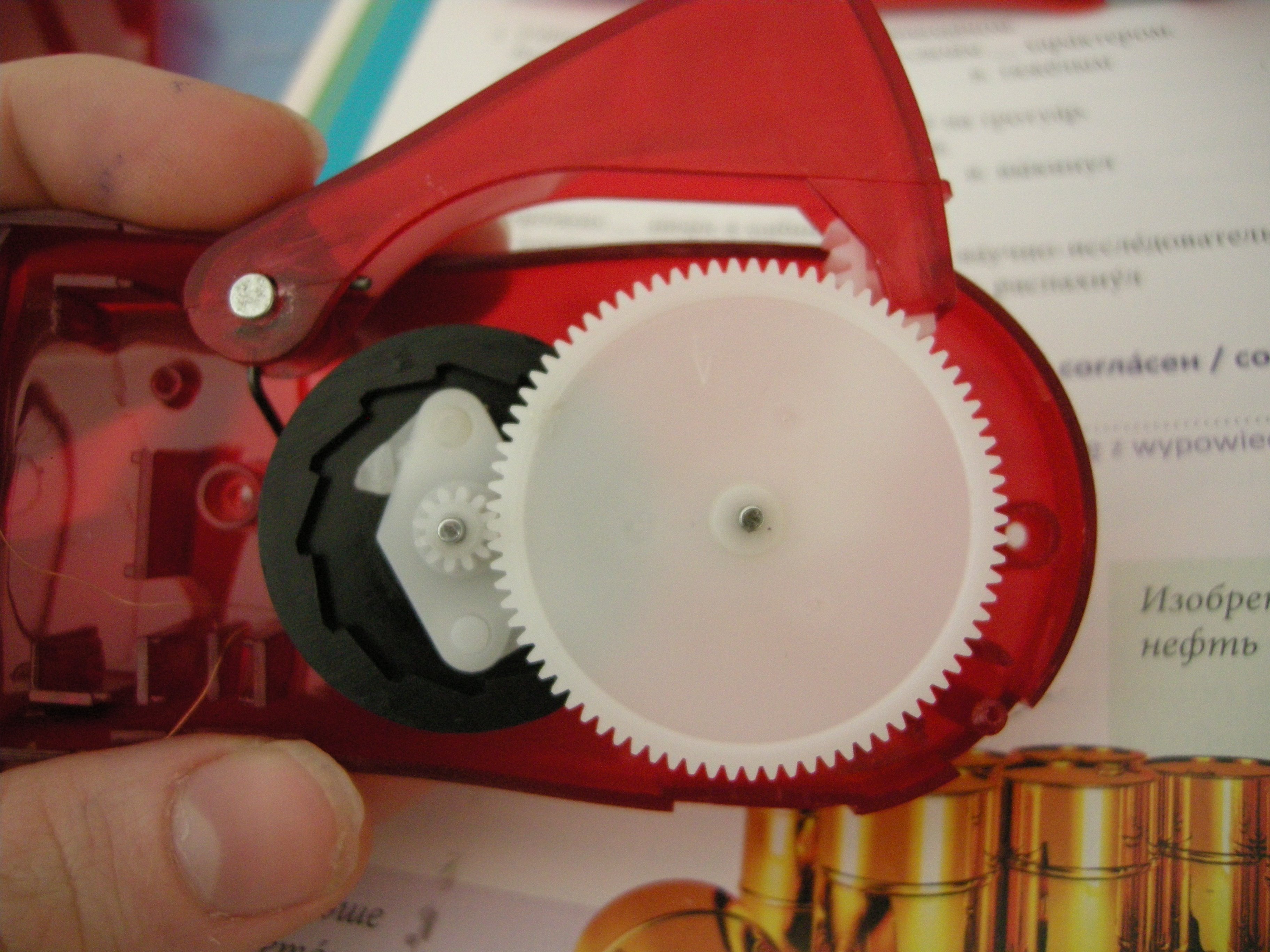
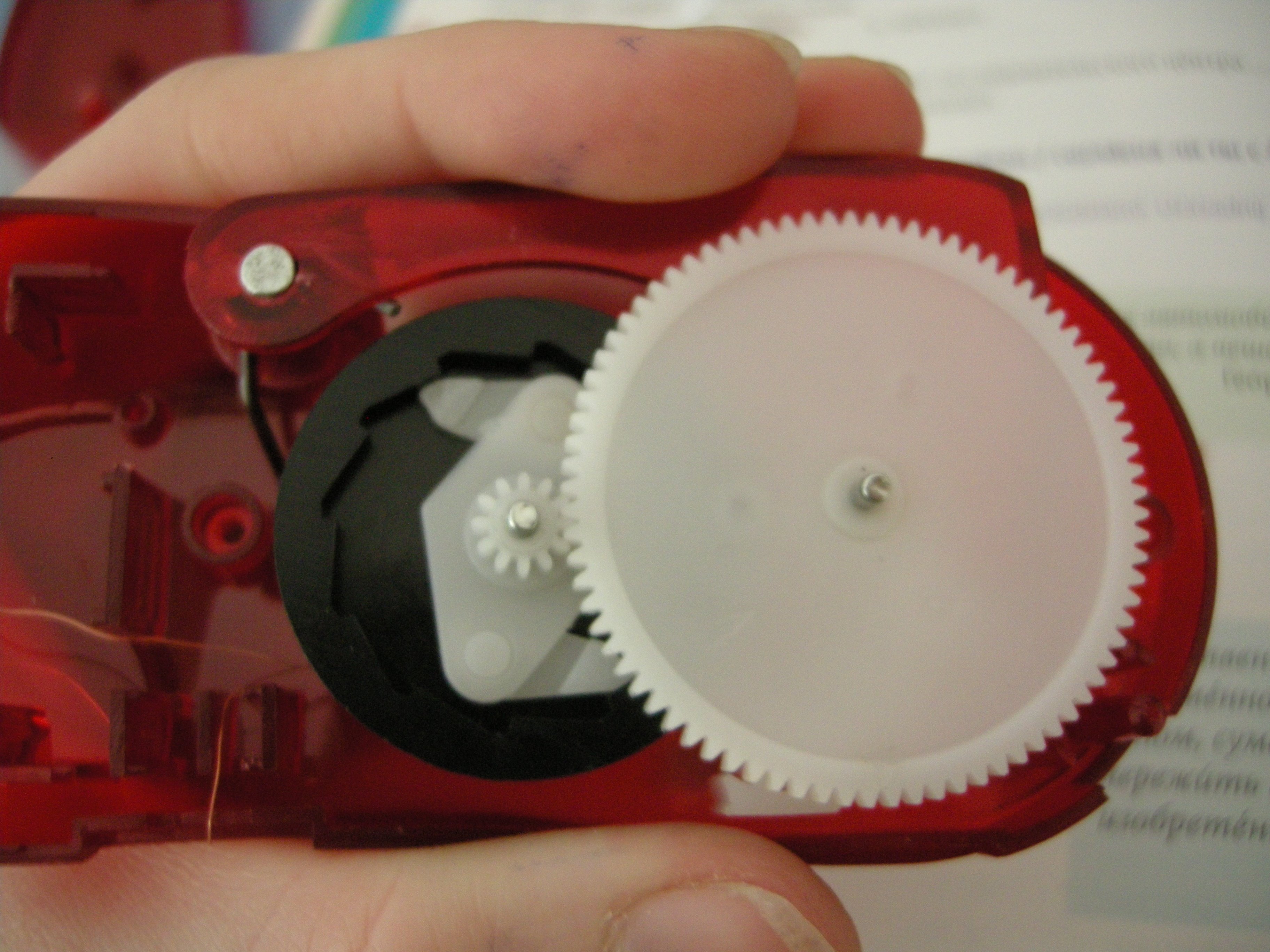
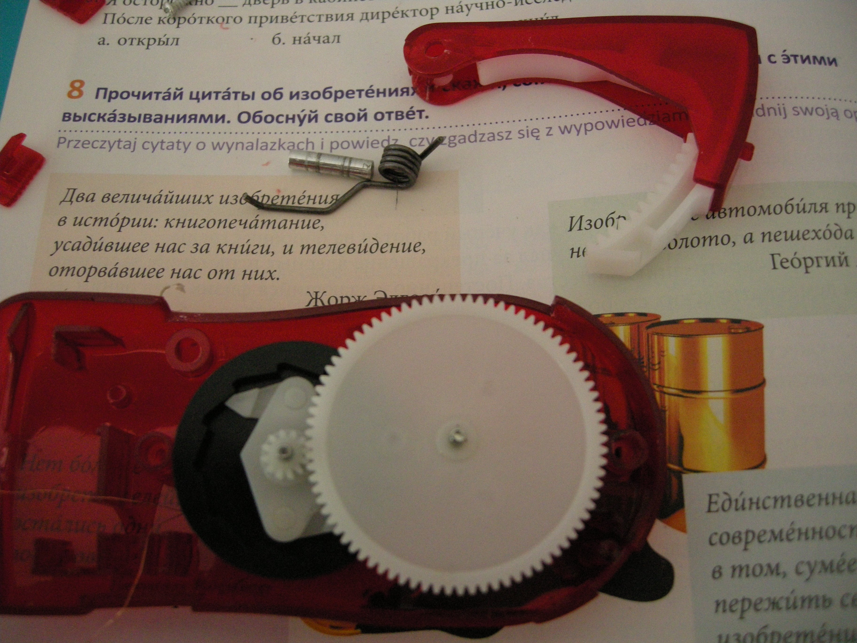
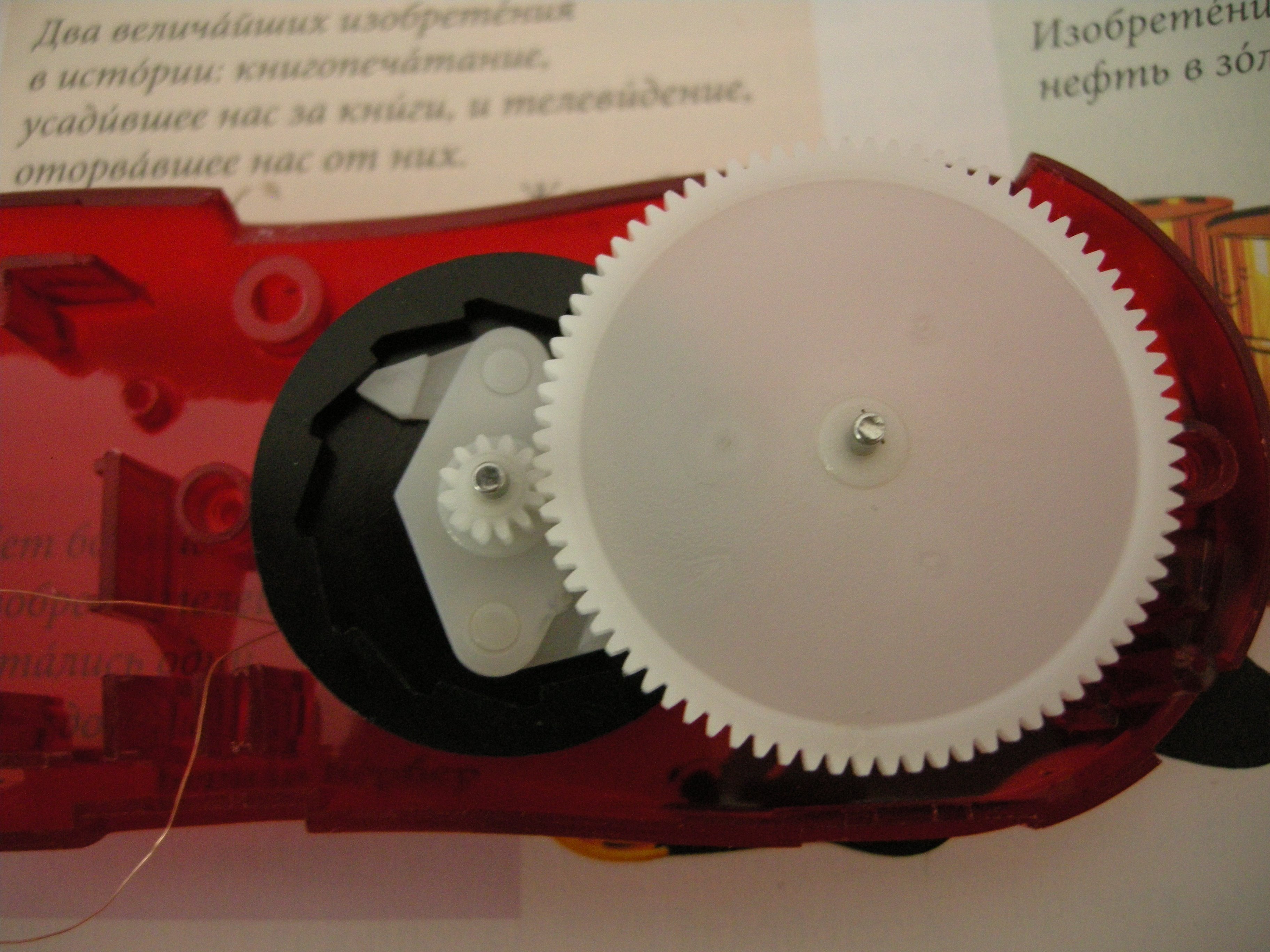
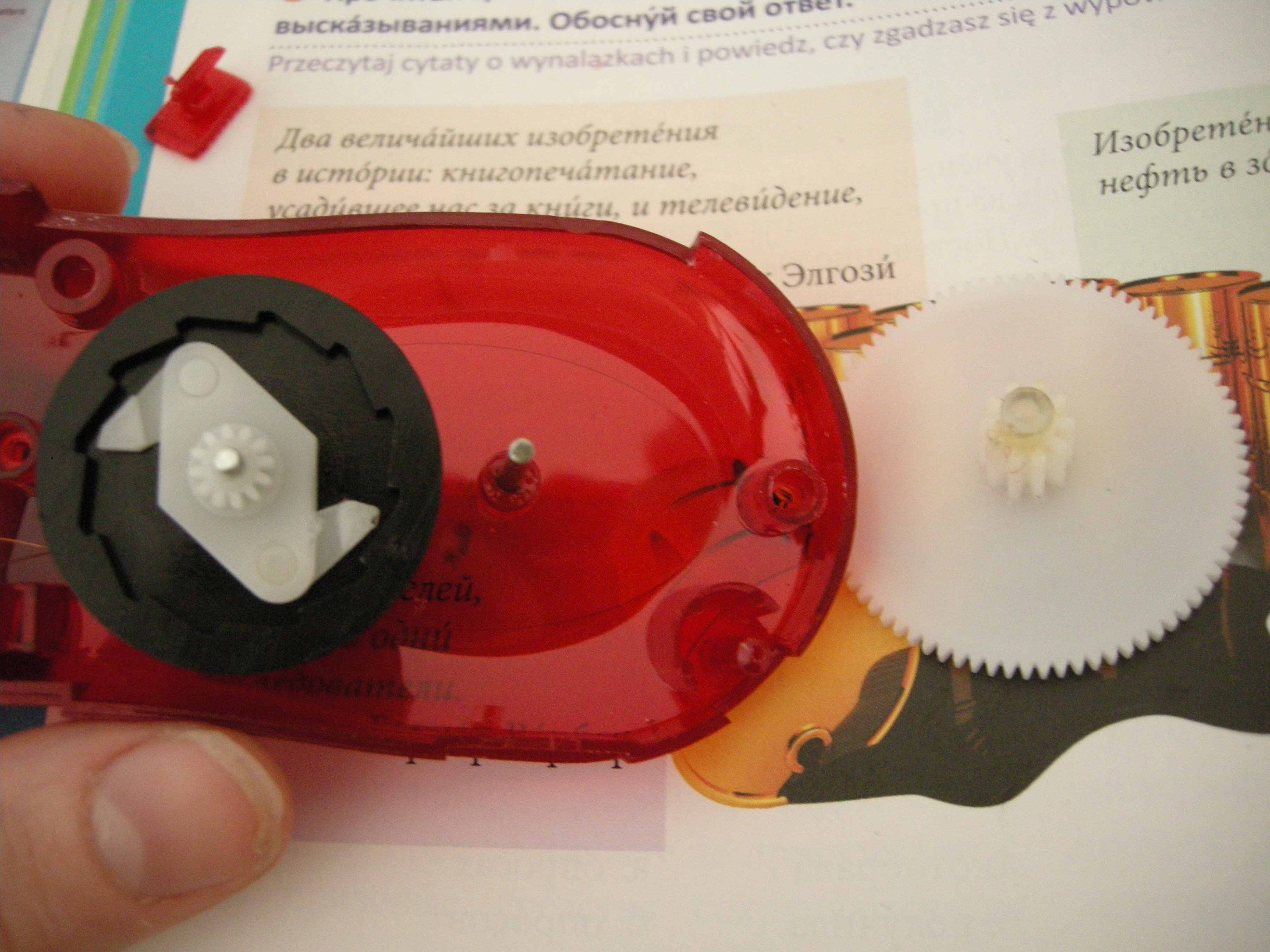
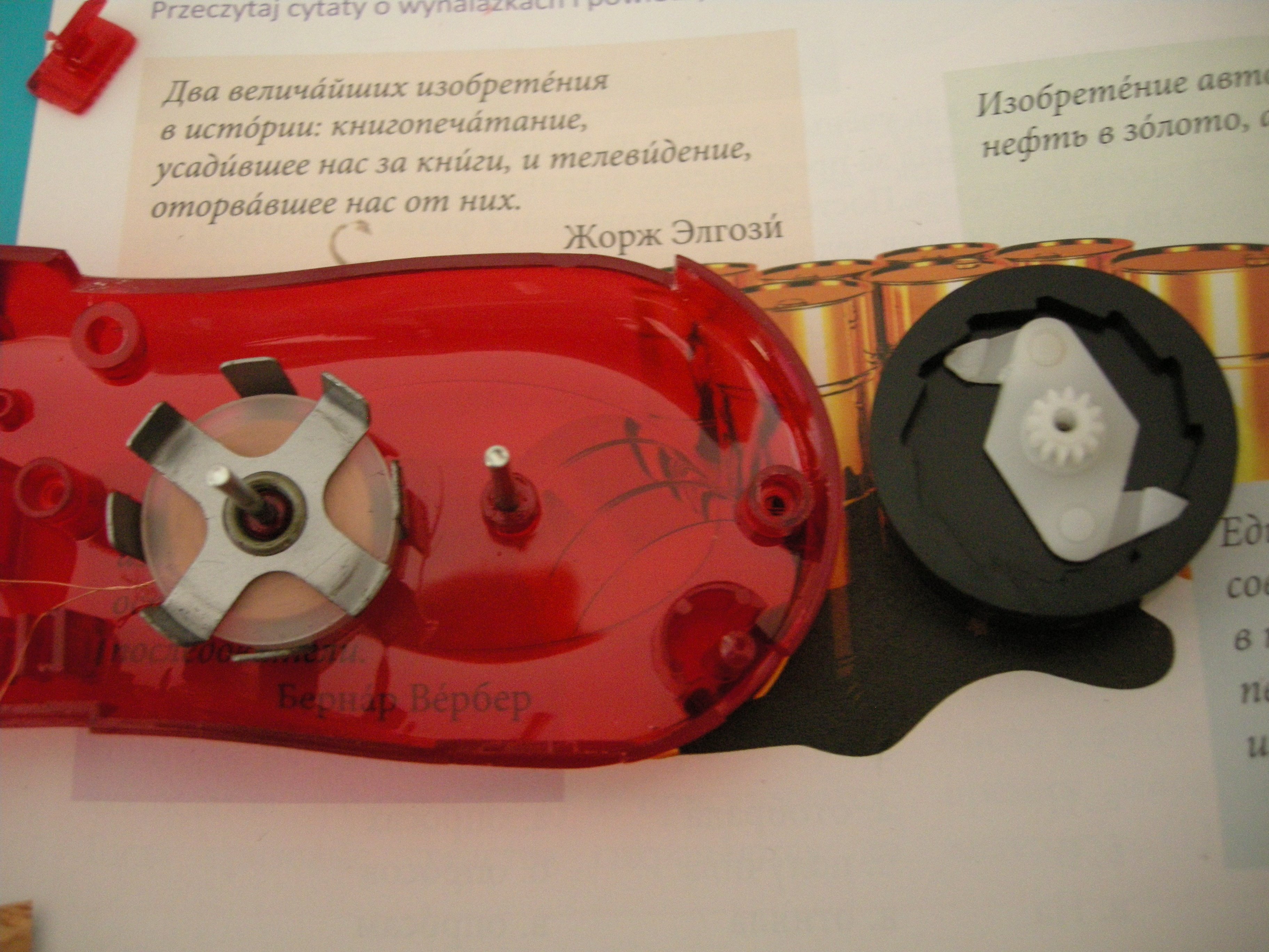
Primary wheel removal. Small wheel interfaces directly with crank, big wheel interfaces with clutch wheel. Also: oily goop!
Replying to @nabijaczleweli
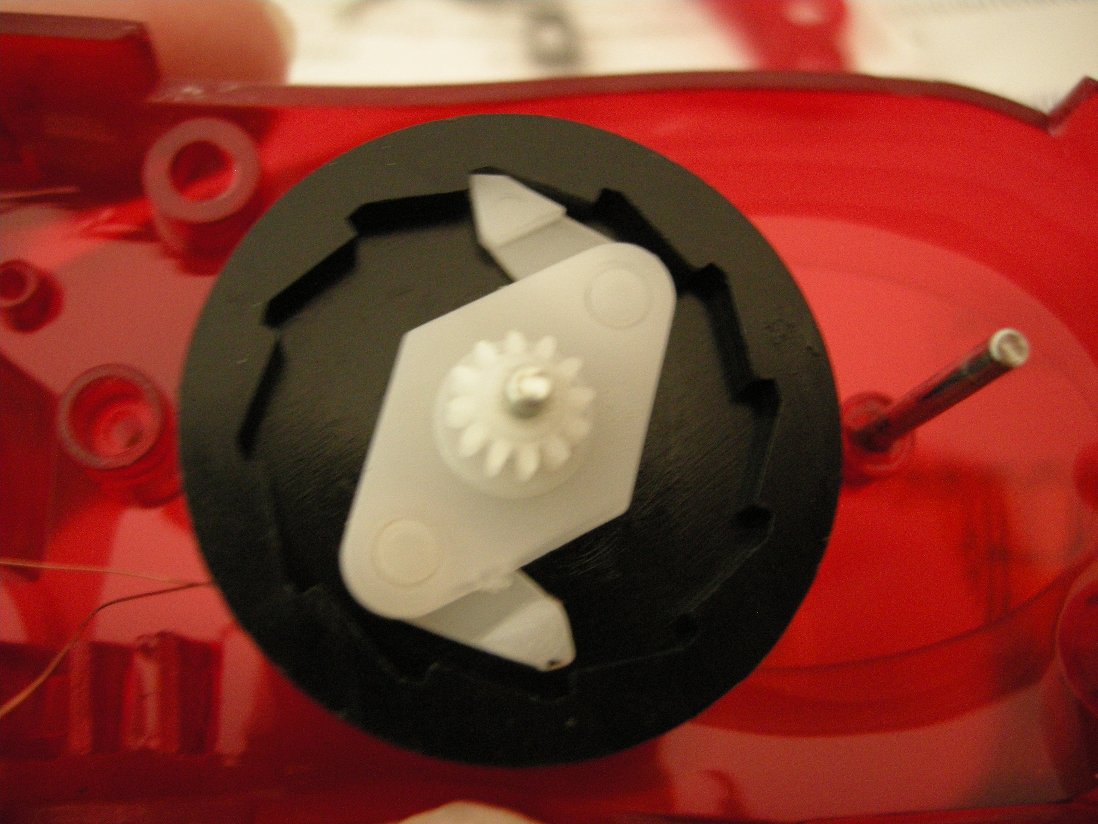
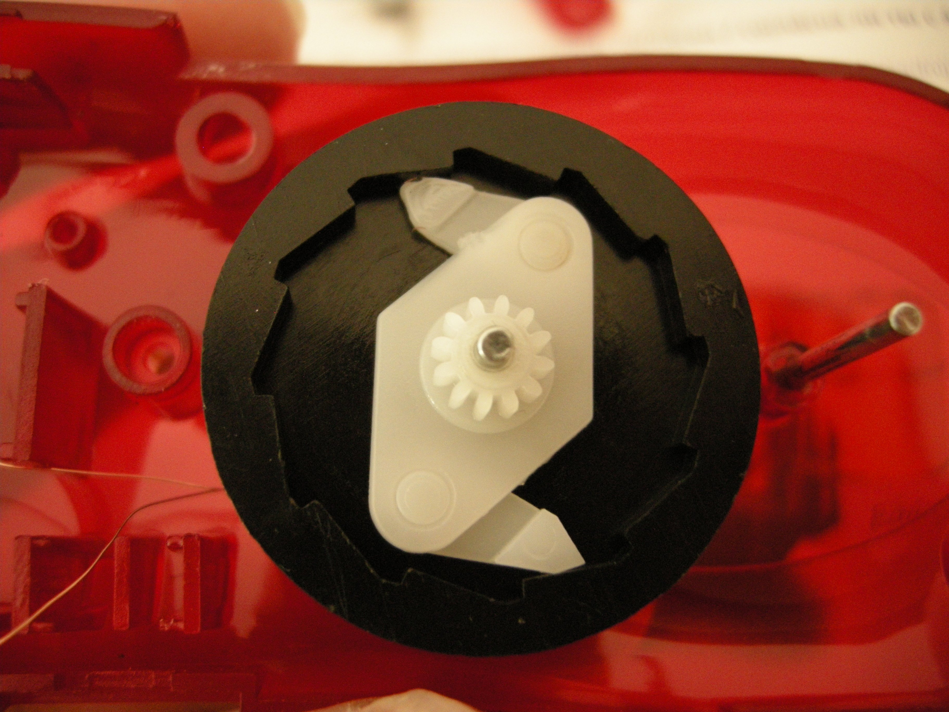
Clutch close-up: engaged, disengaged.
Engages centrifugally when crank pushed and rotates CCW, disengages on CW spring return.
Replying to @nabijaczleweli
Clutch stack removed, the black ring on the underside both (a) reeks of oil and (b) is magnetic, with roughly 8/10 poles?
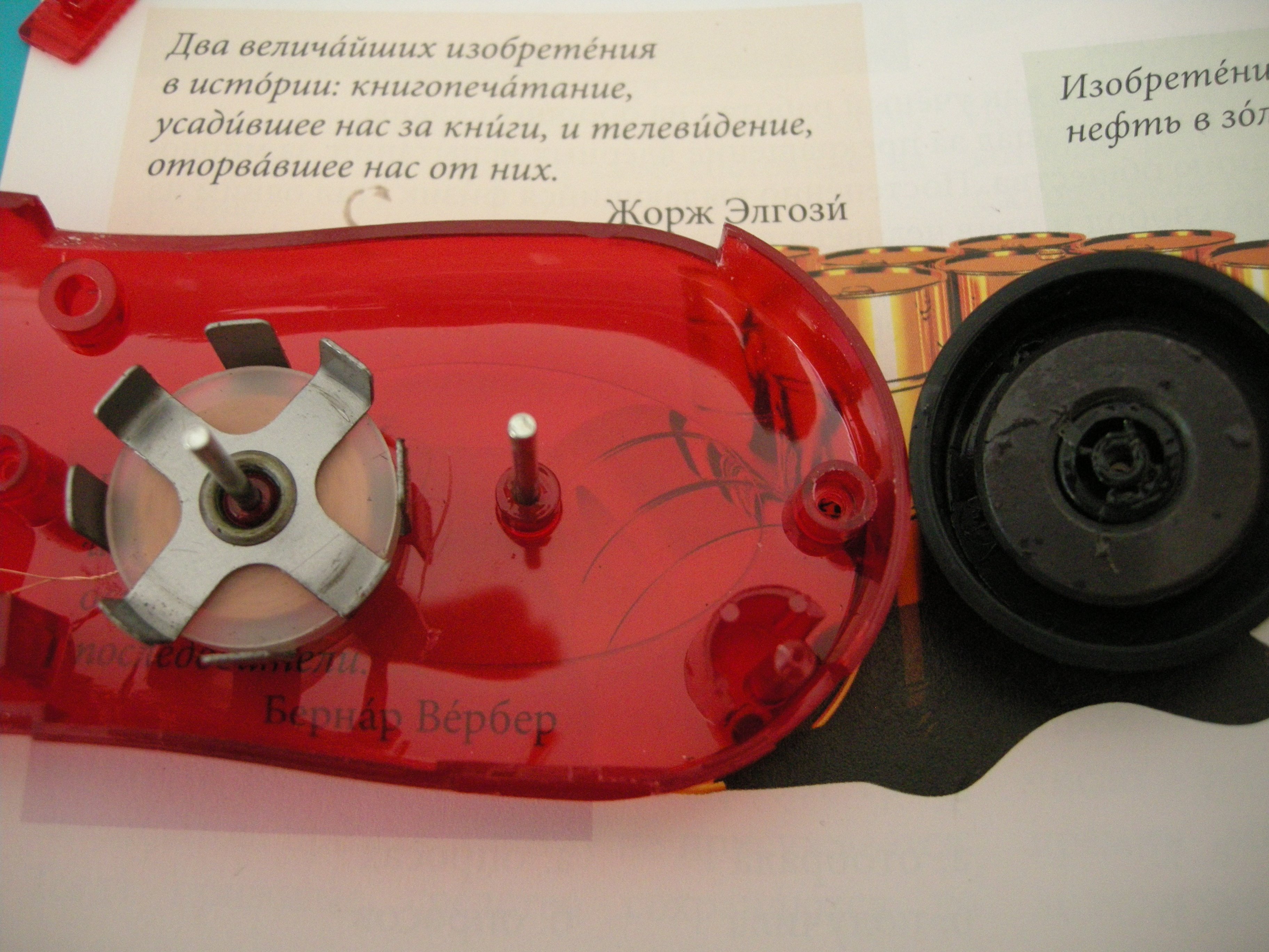
Replying to @nabijaczleweli
All that remains is the coil, which is held in through some weird clamp action on the housing; nothing a bit of Reasonable Force and aforementioned screwdriver couldn't fix, though!
Replying to @nabijaczleweli
Coil, upside-down, notice both the reeky oil and the remnant of the housing inside.
Oh, and also: the strands soldered directly to the LEDs that looked suspiciously like magnet wire? They are magnet wire, and come directly off the coil (bridge would be Too Expensive™/lossy?).
Replying to @nabijaczleweli
Oh, and the clutch just sits loosely on top of the magnet housing.
Replying to @nabijaczleweli
This concludes The Dollarstore Adventures (a.k.a. I always wondered how cost-optimised these lamps are) for tonight!
Replying to @violent_meals
wouldn't it be Юровская (Yurovskaya?) tho
Replying to @violent_meals
well on one hand sure but on t'other Юровский is the m version and Юровская is the f version ya feel
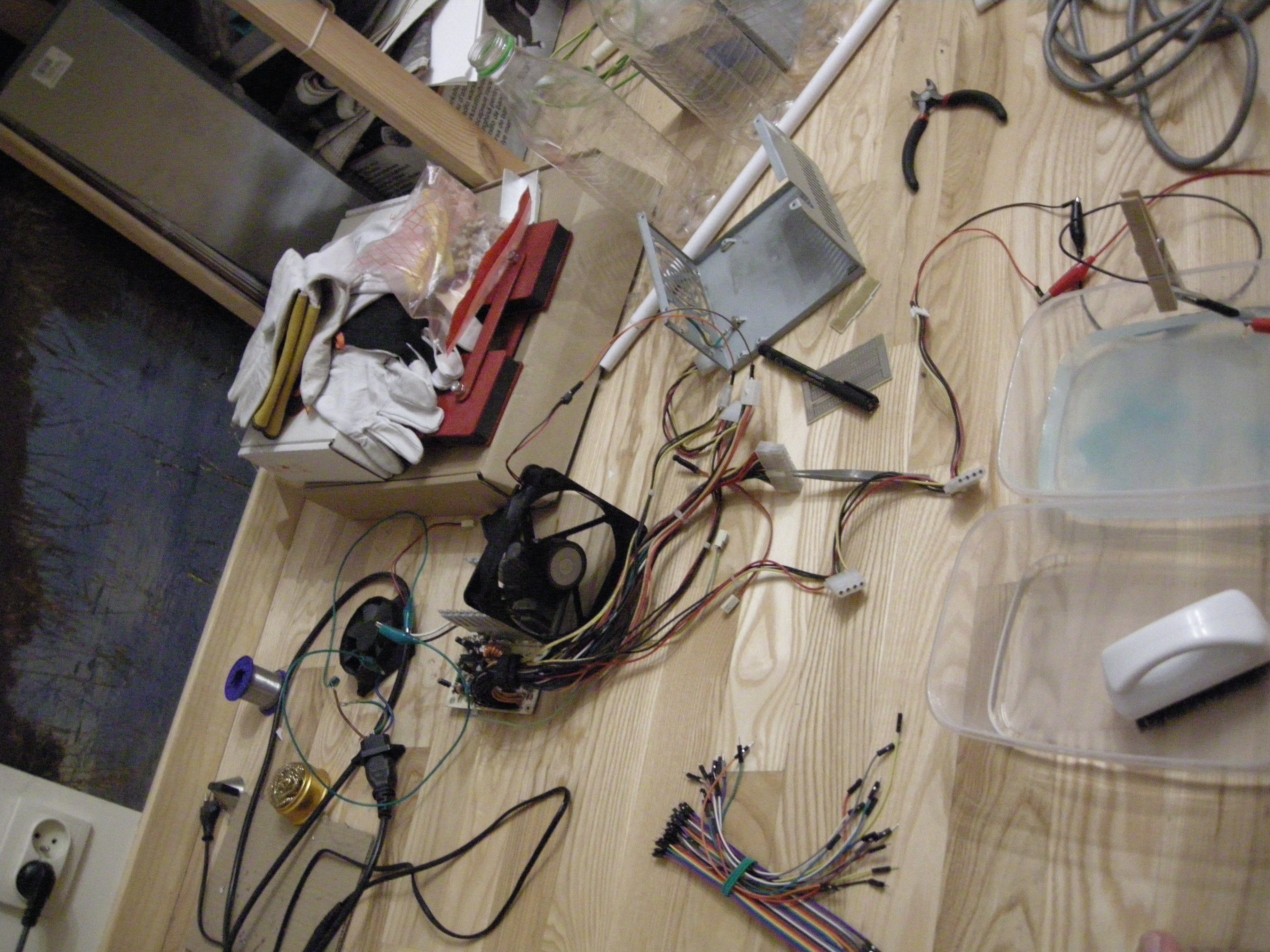
Step One: get a permanent waterproof marker, some laminate and a hacksaw (not pictured); attempt not to cut off your thumb nor your calf
Replying to @nabijaczleweli
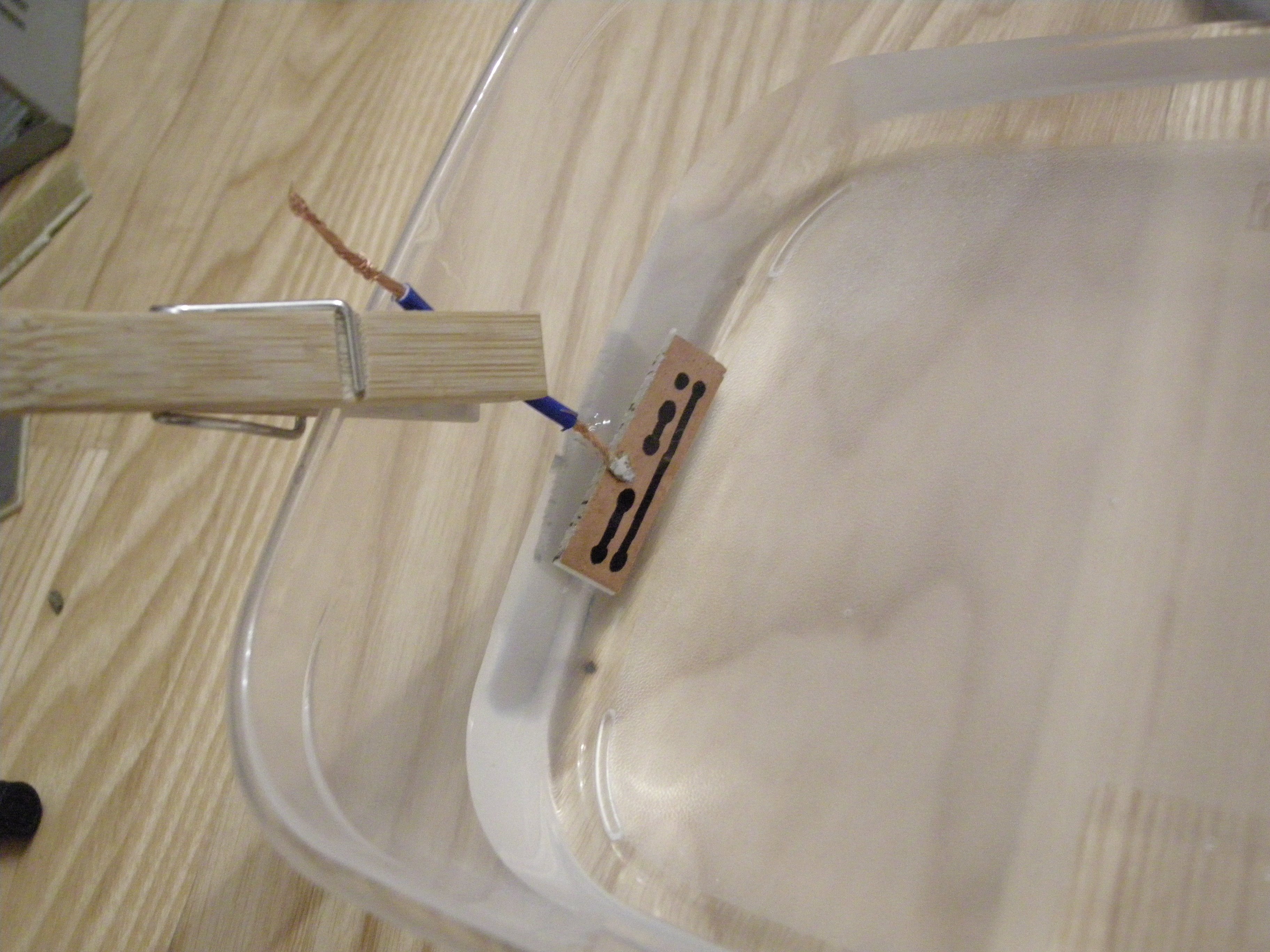
Step Two: attach one (1) piece of trash wire recovered from a car installation to the laminate cut-off
Replying to @nabijaczleweli
Step Three: insert one wooden thingy and two "that's probably okay"s of water (not pictured) into some Indian Polypropylene

Replying to @nabijaczleweli
Step Four: mount trash to Indian with springy
Replying to @nabijaczleweli
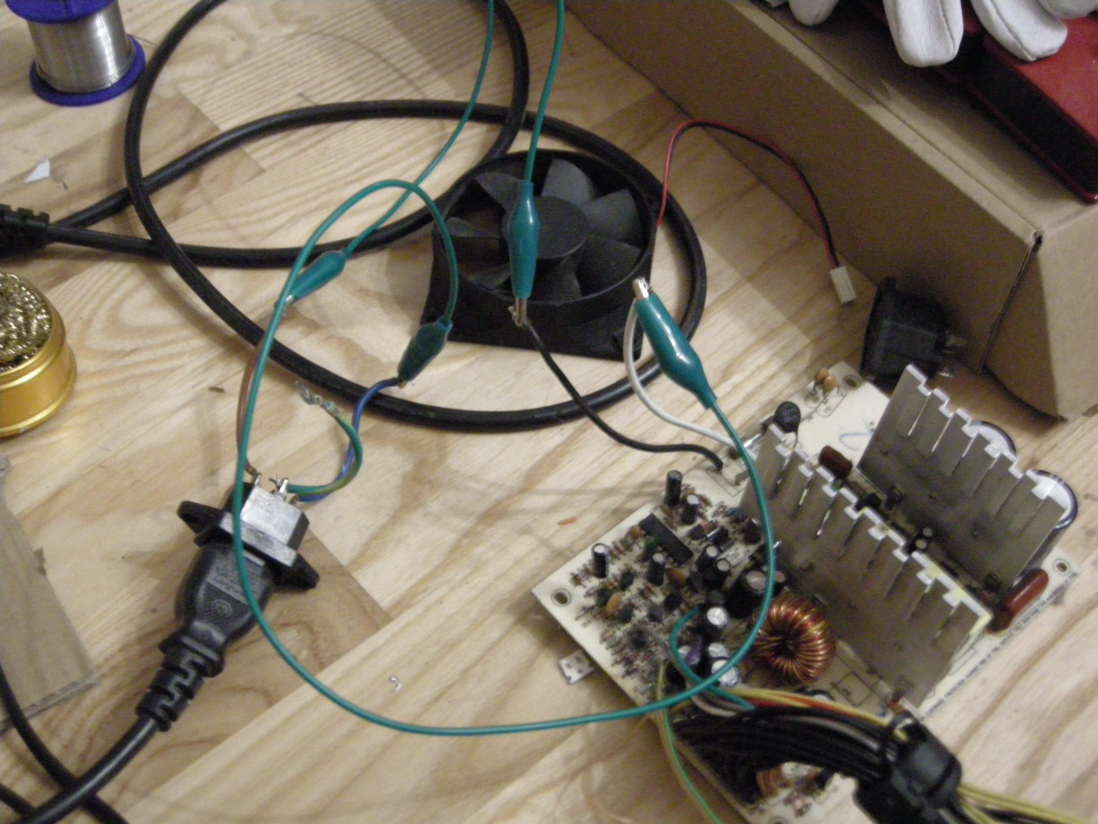
Step Five: assemble death trap (yes it's still the same PSU from last time, I'm trash)
Replying to @nabijaczleweli
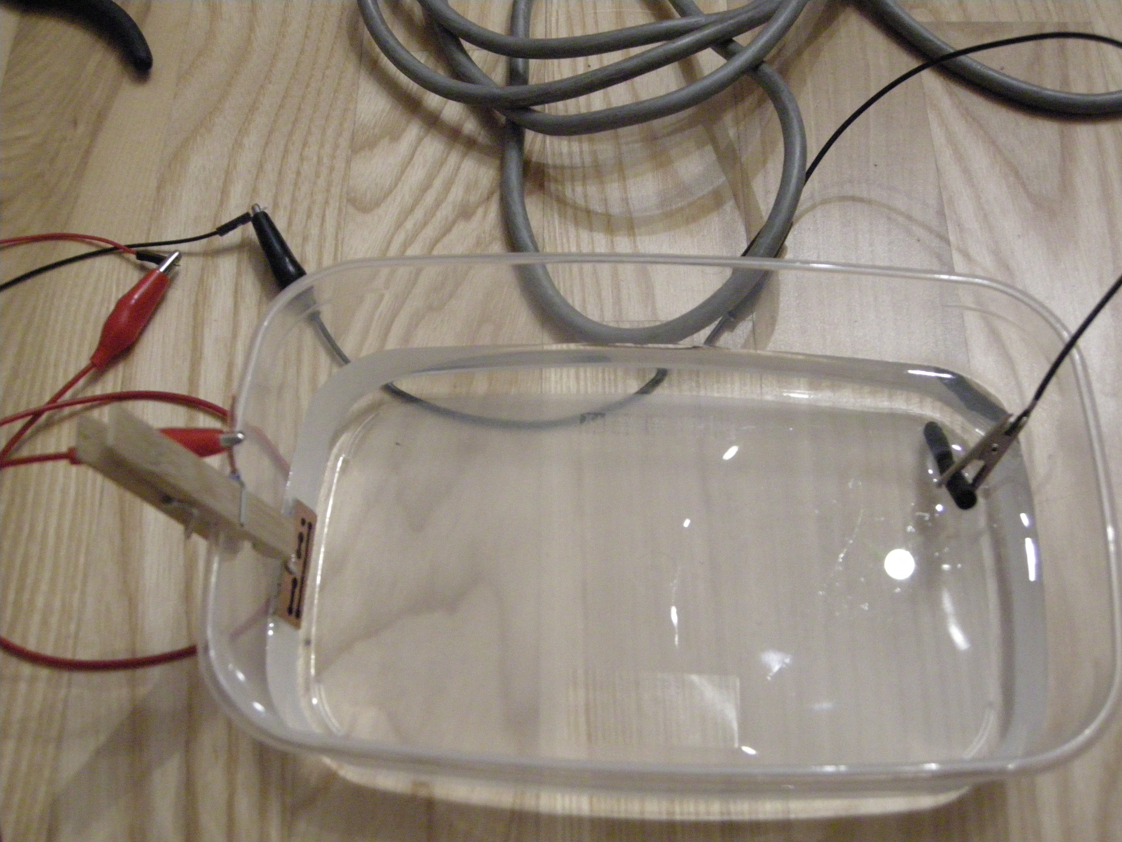
Step Six: attach carbon rod from a battery to the negative and trash to the 12V rail, short enable to ground with tweezers, look at bubbles
Replying to @nabijaczleweli
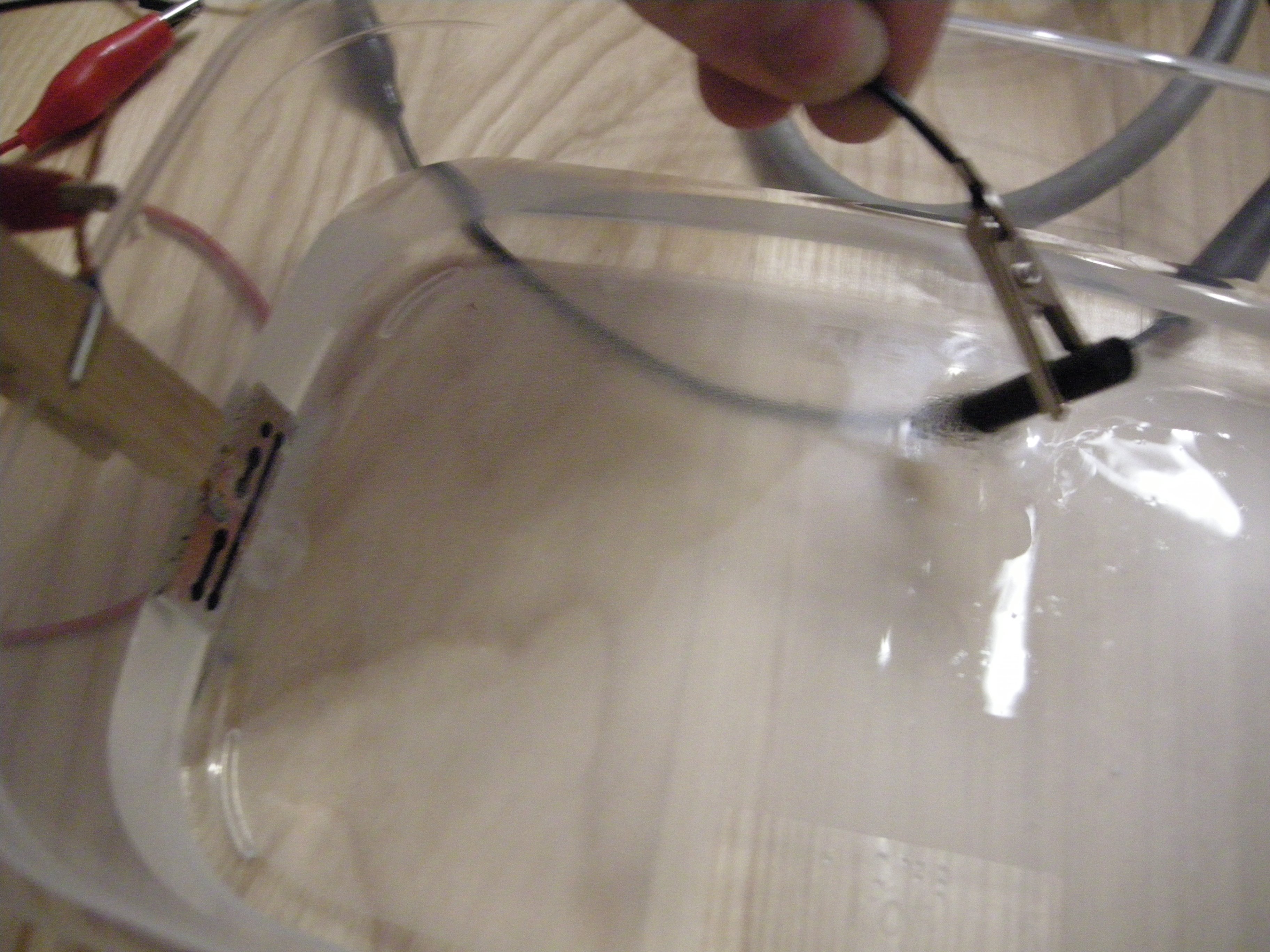
oooh look at the copper-blue wisps, neat
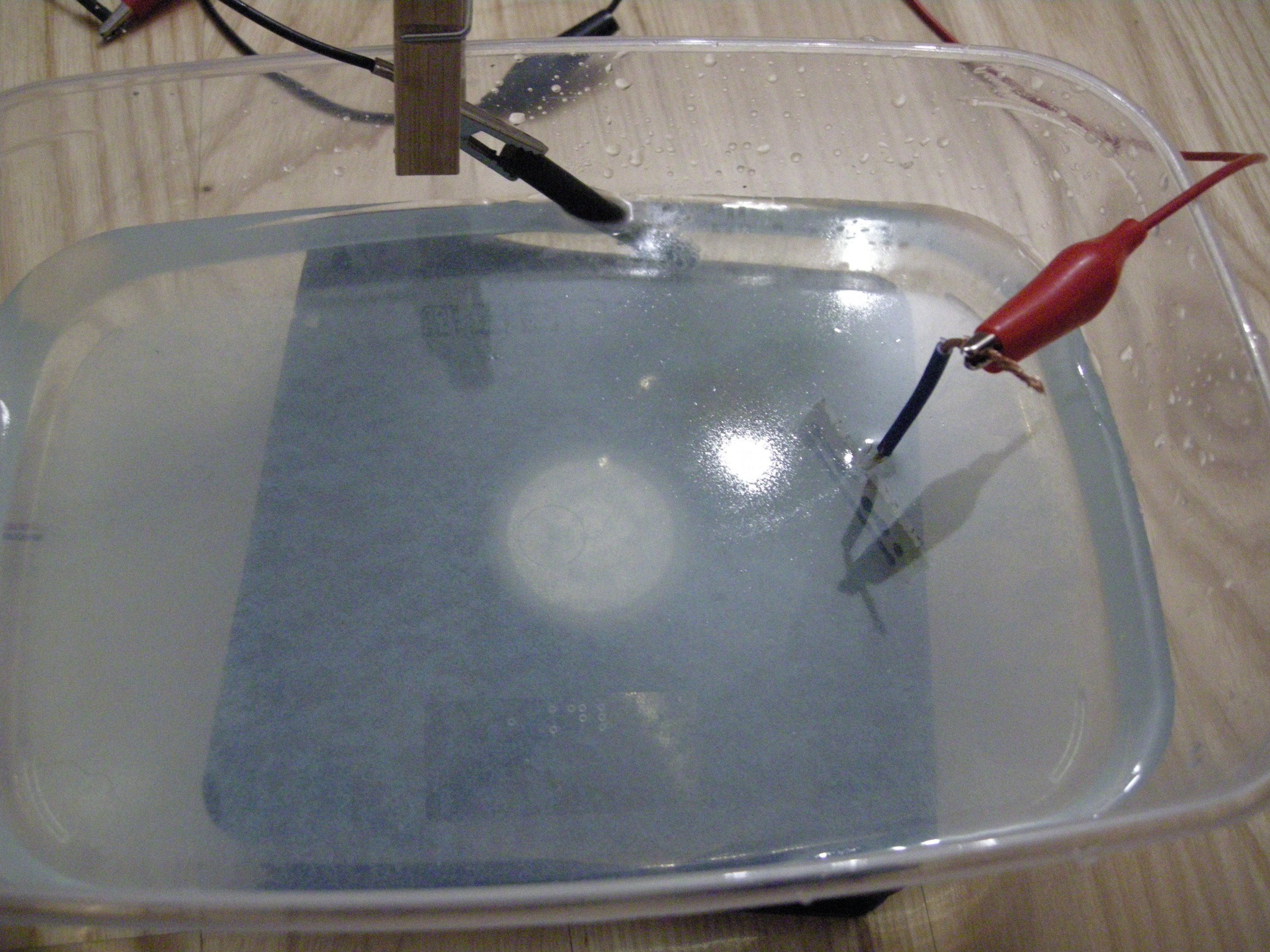
Replying to @nabijaczleweli
Step Seven: assess what an absolute state this is
Replying to @nabijaczleweli
Step Eight: wipe the laminate with a brush and decide that this is not going anywhere anymore
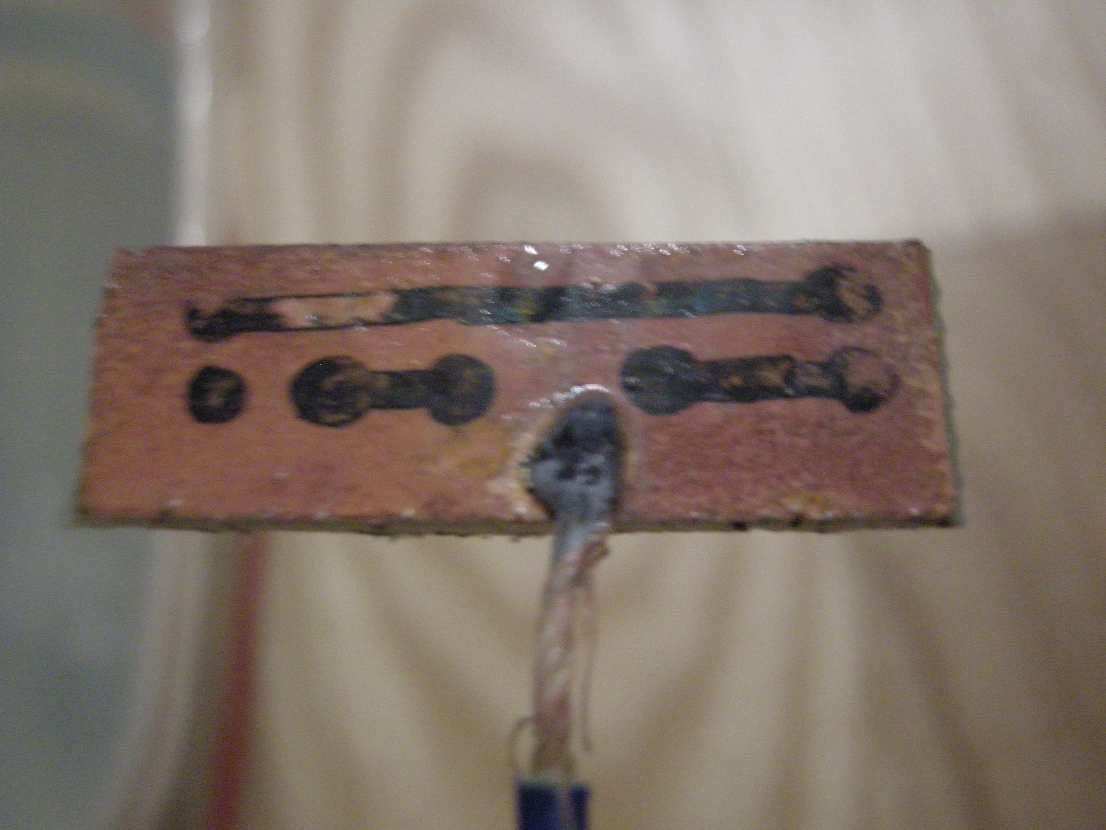
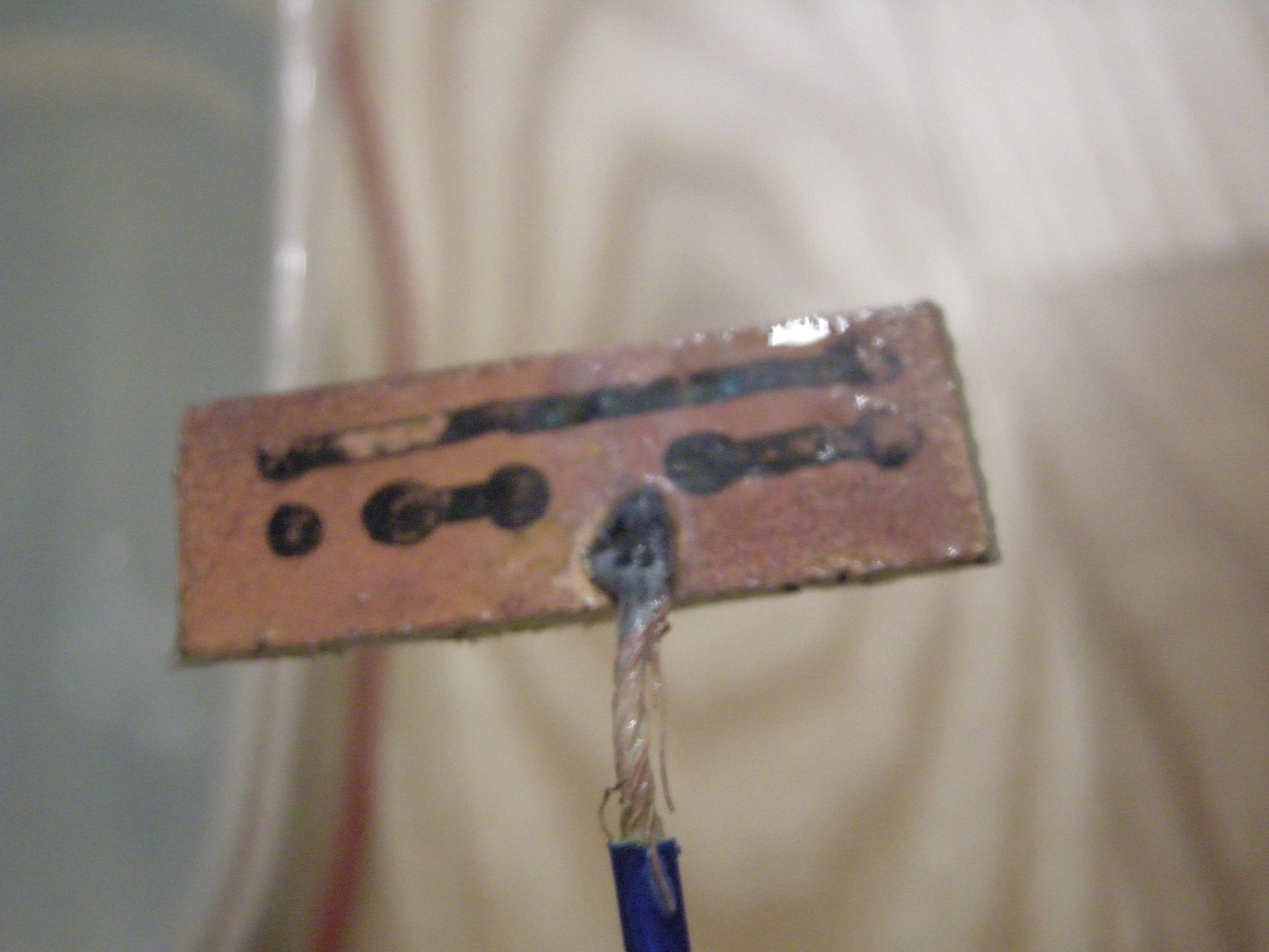
Replying to @nabijaczleweli
Step Nine: reach the conclusion that you're too trash for electroetching and would probably need a better process to get anywhere with it
Replying to @nabijaczleweli
This would probably've worked better with a more active etchant but the only other thing I have rn is conc. sulfuric, which would turn this from "unproductive electroetch attempt" to "local moron dies from breathing hydrochloric"
Replying to @nabijaczleweli
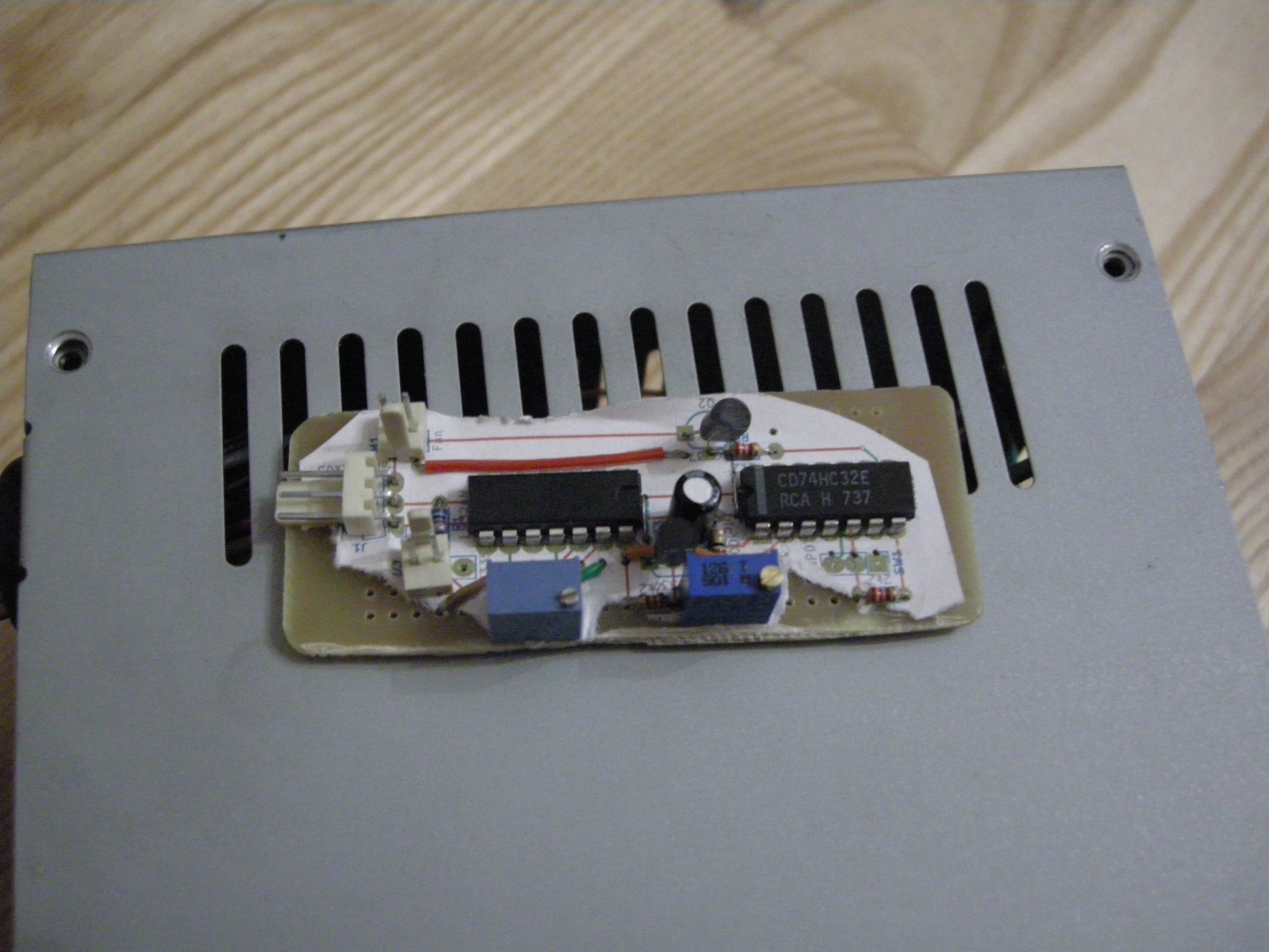
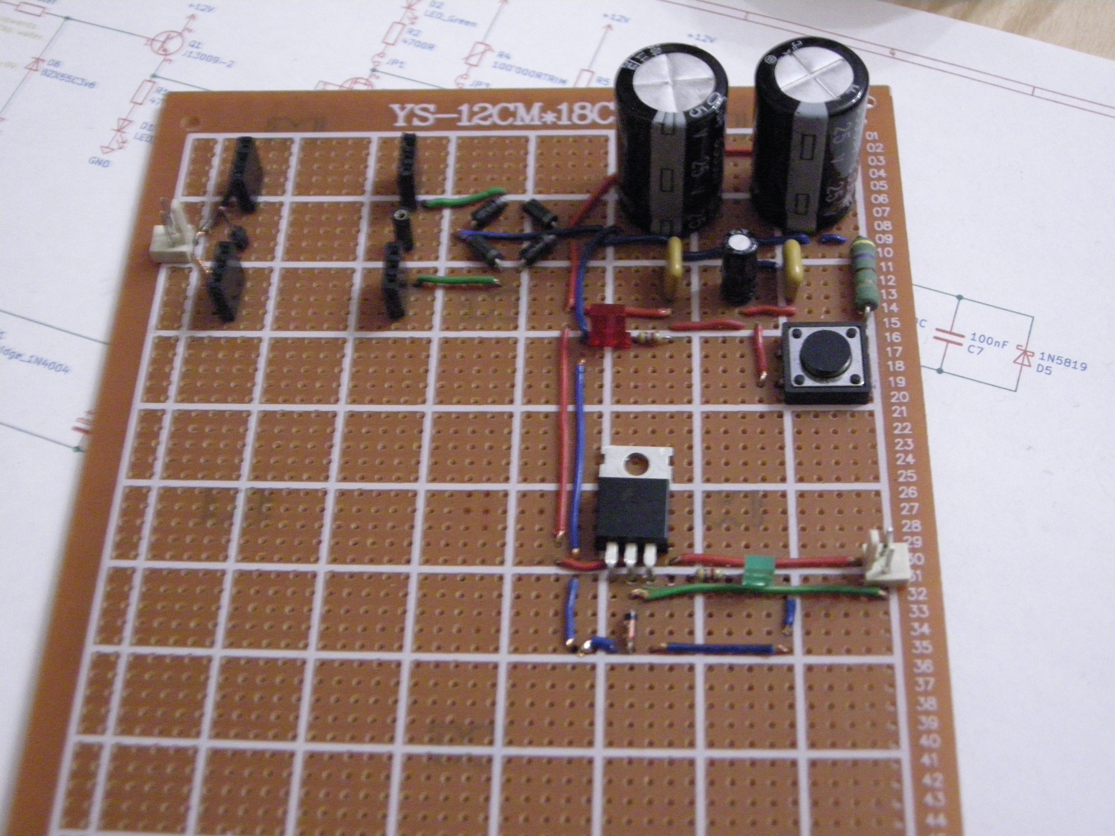
If I had more than a quarter of a fucking brain I would probably have designed the board with the packing considerations in mind, but now it's built and doesn't fit into the socket holes anywhichway so it seems like a visit to bodge town is in order
Replying to @nabijaczleweli
So now there's a problem to be solved: where in the ever-loving hell is this thing gonna go? I can see two options: (1) on the top plane, over the output cabling, near the wobbly AC in, or (2,3) on the side, over the mains caps.
Replying to @nabijaczleweli
However, this means I'll have to go through the cover (and prolly replace keyed headers with flat ones). Now, the side location doesn't look all that bad (1), but the only place with enough clearance on the top is also sadly where the main out vent is (2), so over the HV it goes!
Replying to @6b766e
like "каш" :v
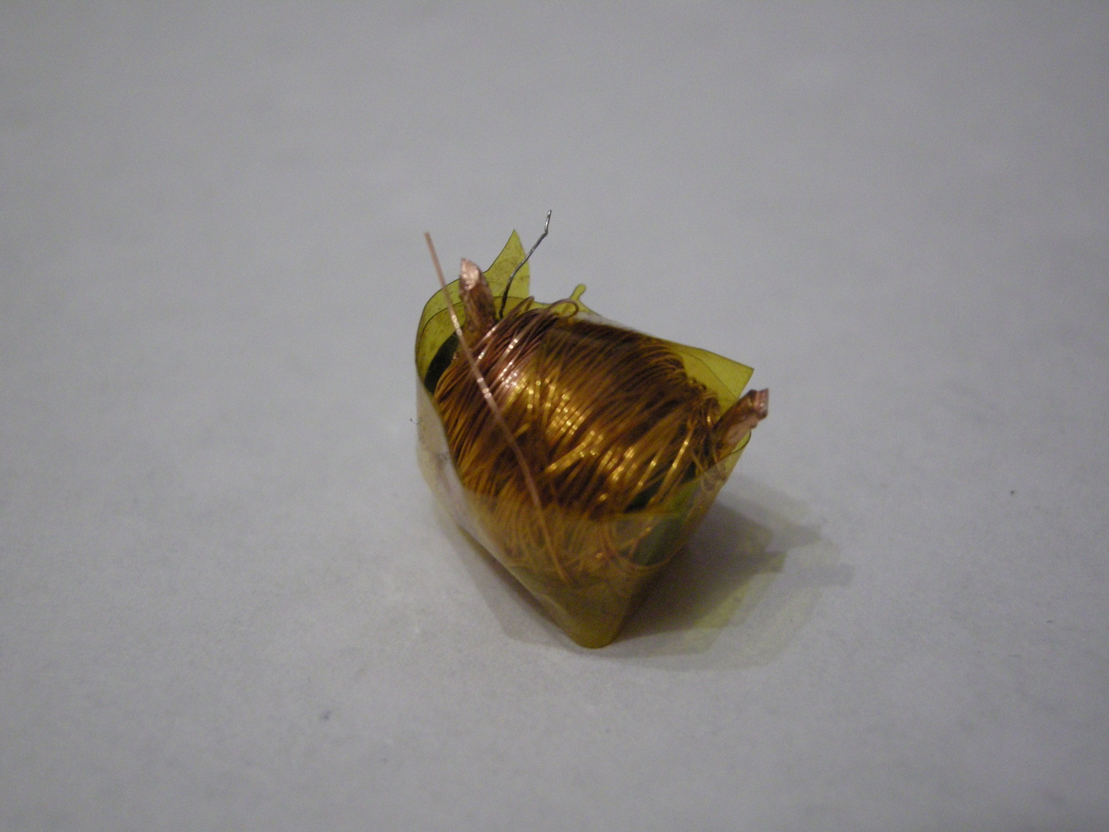
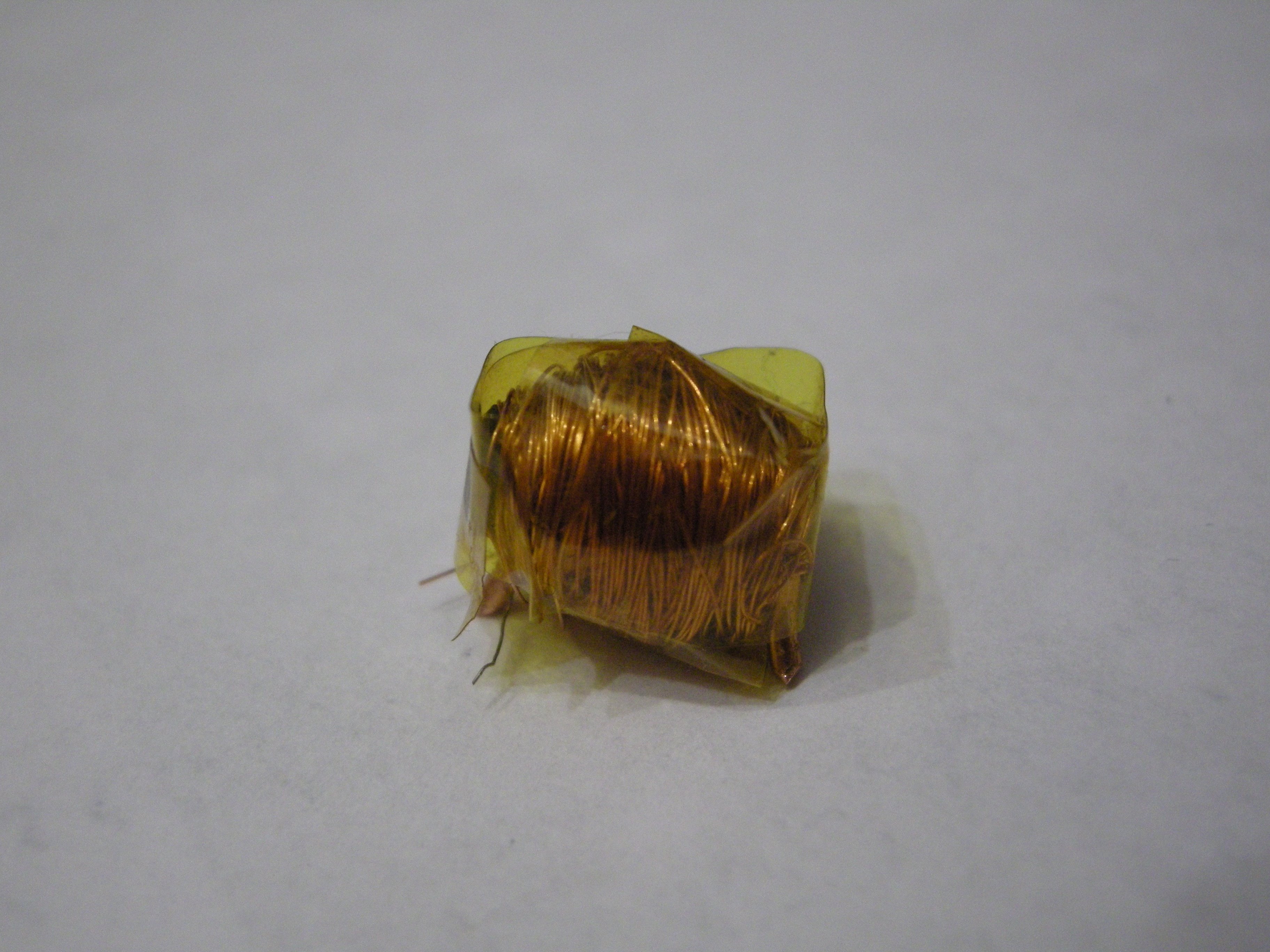
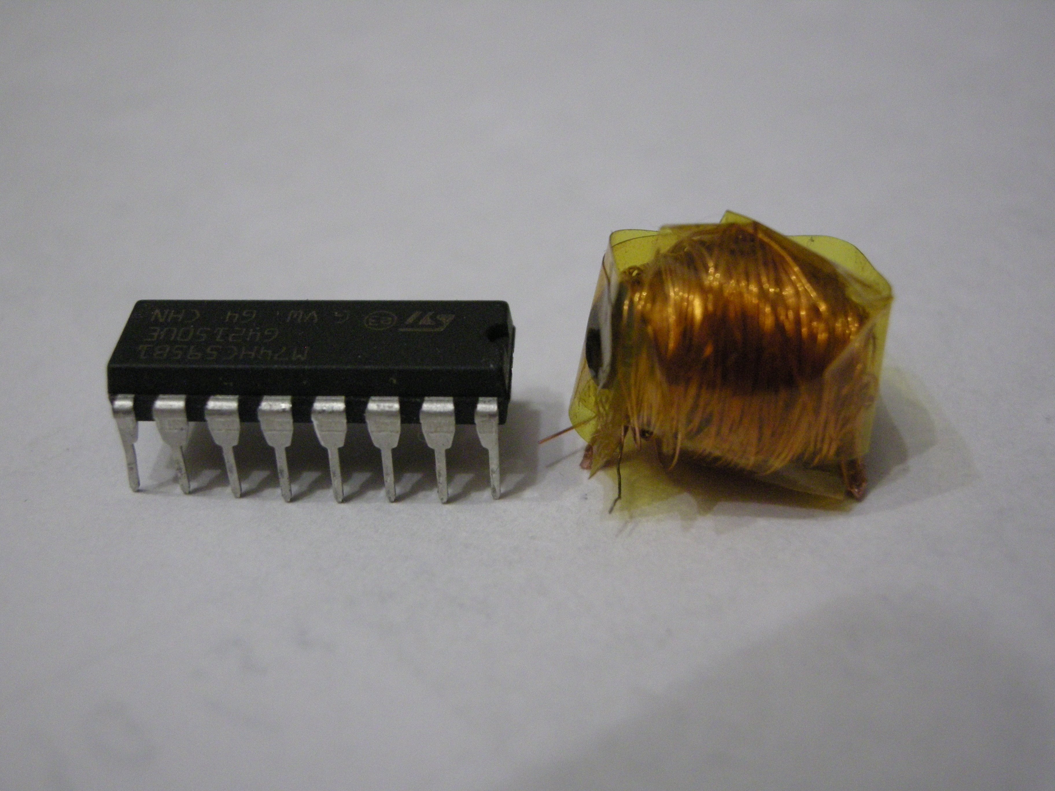
hash-tag transformer thursday or sth

Replying to @nabijaczleweli
7 to roughly 250 turns, original core and primary from some PSU probably, secondary from the previously featured LED crank lamp https://twitter.com/nabijaczleweli/status/1113121372010577921
Replying to @nabijaczleweli
yes I have a lot of russian homework rn how did you kn o w
You know it's been a productive evening when the main takeaway is "maybe I'll not lose my right eye" (hopefully)
Replying to @nabijaczleweli
Also: this trash https://twitter.com/nabijaczleweli/status/1116424208907669505? yep, it's trash (probably, I don't have a cap rated high enough to check, but it's def. not enough as a dump inductor).
Replying to @nabijaczleweli
OTOH: a 240/12V@500mA transformer ran at 3A? Less trash, managed to get A Spark across the flash electrodes (and another one across the primary switch but hey it's Progress, going up to the 20(?)mm).
Granted, it did go up to the best part of fifty degrees, but what can ya do.
Replying to @nabijaczleweli
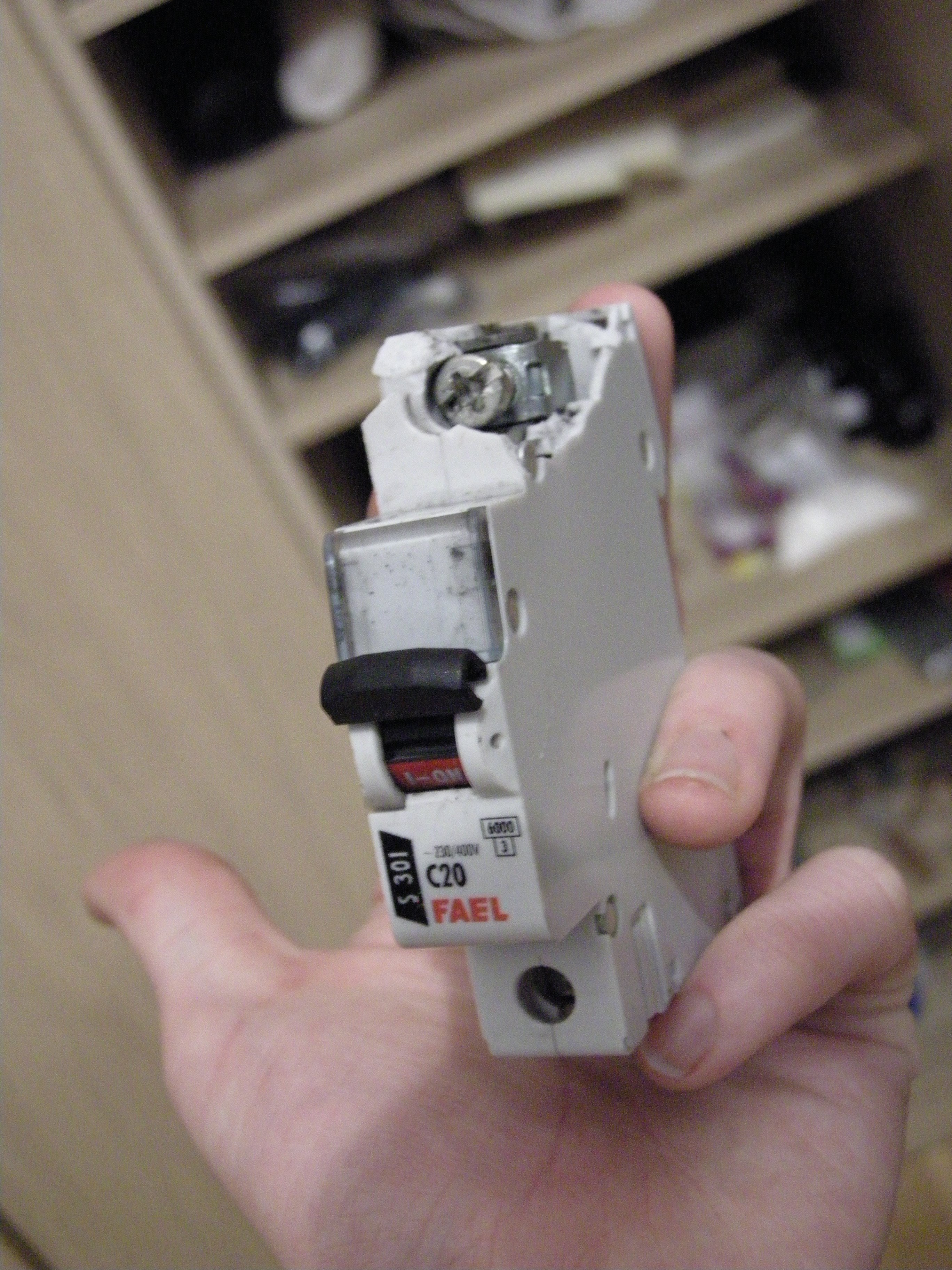
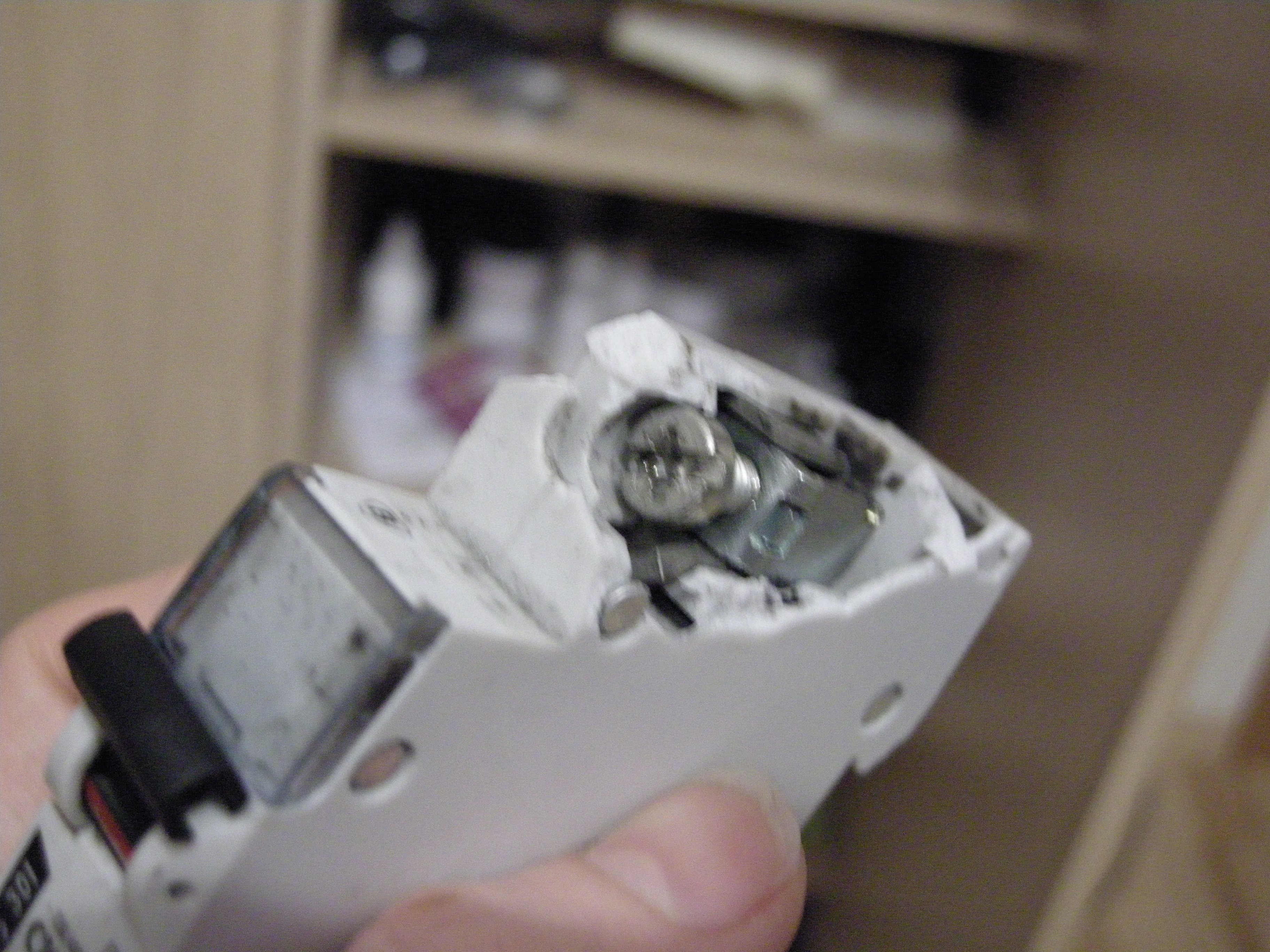
Today in doing Very Smart Things (yes that's a hole right through the clip, yes I blew two breakers).
In unrelated news: driving that transformer from mains did not work for some reason, with the rectified voltage at the output shooting up to ~100V then discharging 🤔
Replying to @__vlqc
🤔 https://crates.io/crates/lovecraft
Replying to @thecoshman and @tweetsbi
it's almost as if individual employee satisfaction which yields to higher capital gains in the long-term is oft^W always thwarted by capitalists in order to acquire higher short-term gains, even as a means to a destructive end 🤔
Replying to @thecoshman and @tweetsbi
Introduce artificial scarcity (a.k.a. KPIs/bonus systems or w/e) and it gets a whole lot cheaper /and/ works just as well, if not better (spite's the best motivator, innit).
Replying to @tweetsbi and @thecoshman
Companies with a set goal (that isn't "generate capital") also survive longer, thereby generating more income in the long term, but :v
Replying to @nabijaczleweli
Nope, not sketchy at all!
Replying to @nabijaczleweli
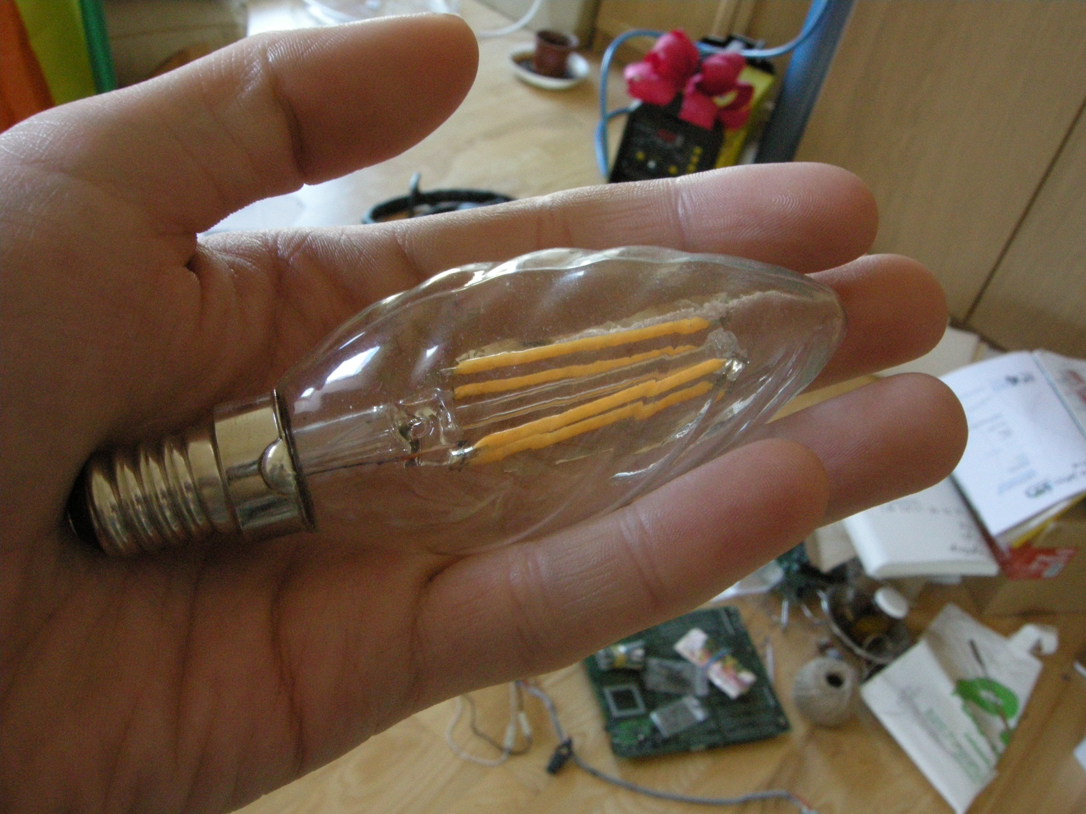
Aaaaand back to where we were before I fucking smoked it (not pictured: 3 months' worth of dust)
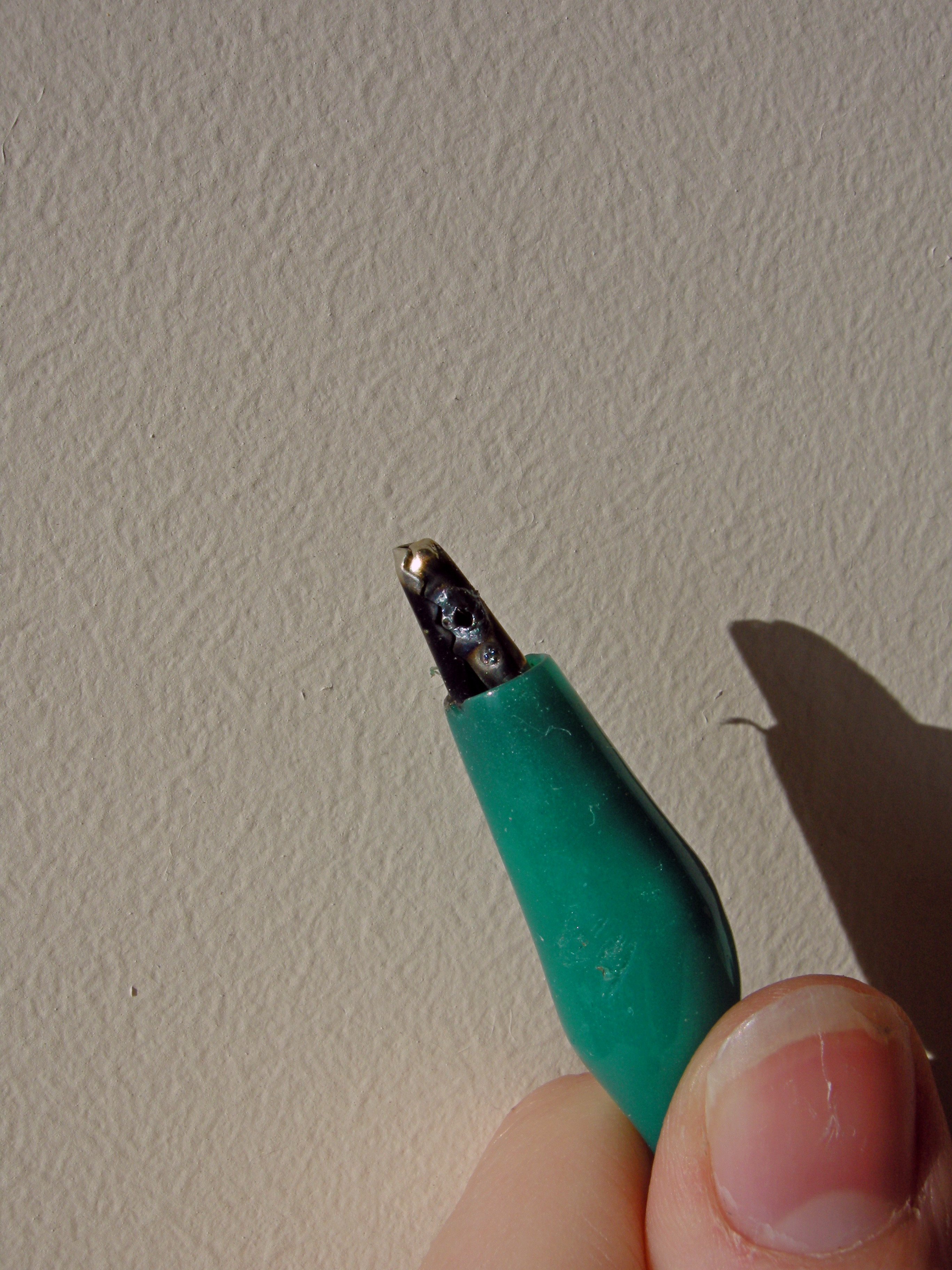
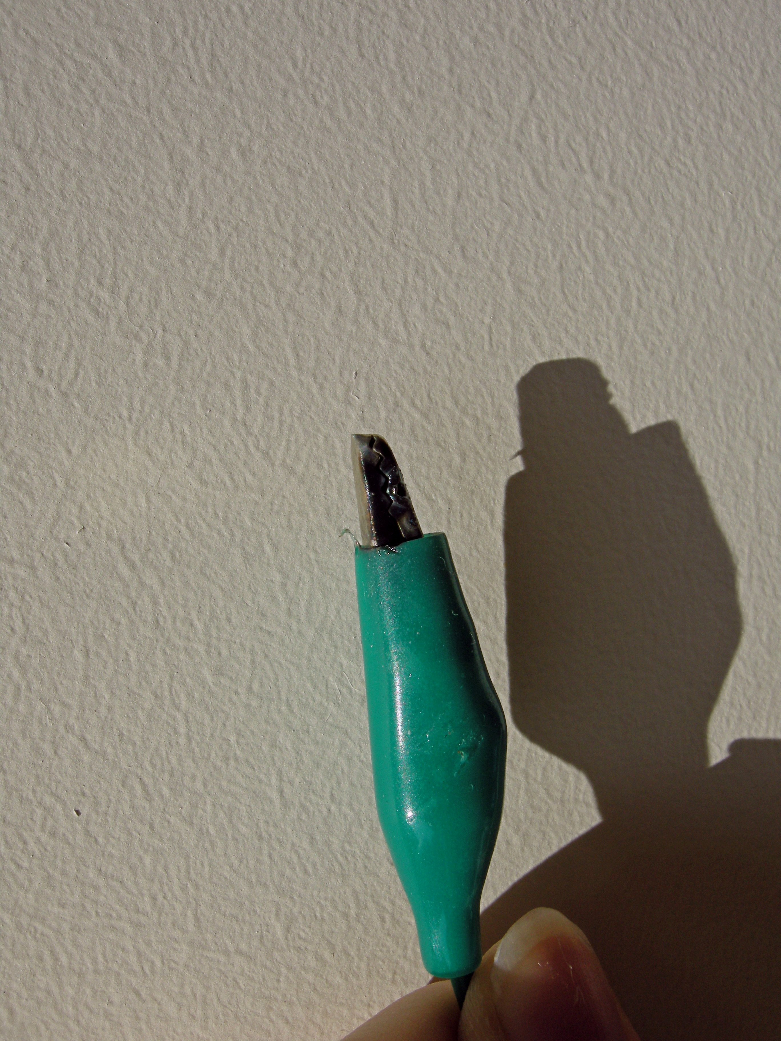
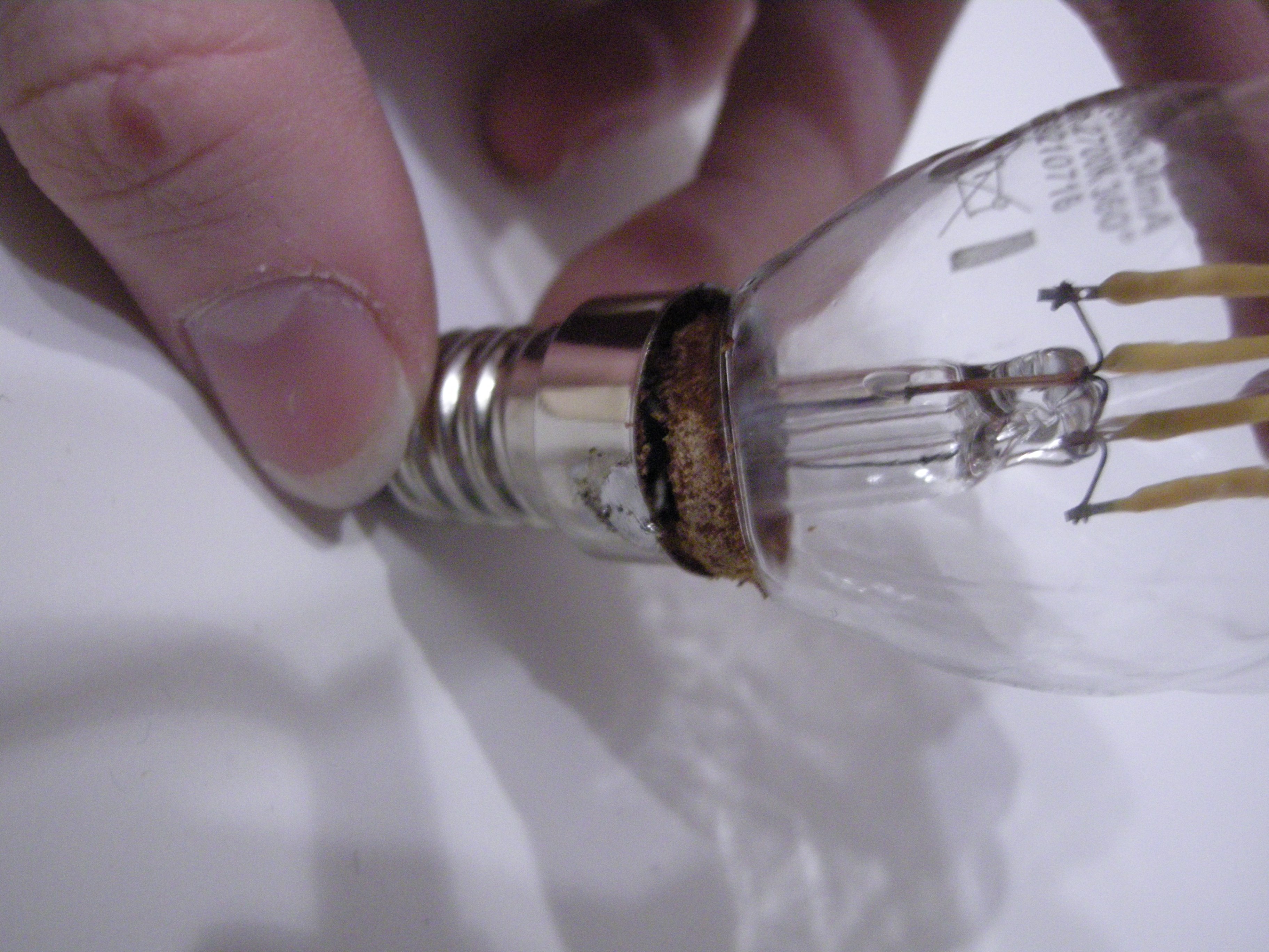
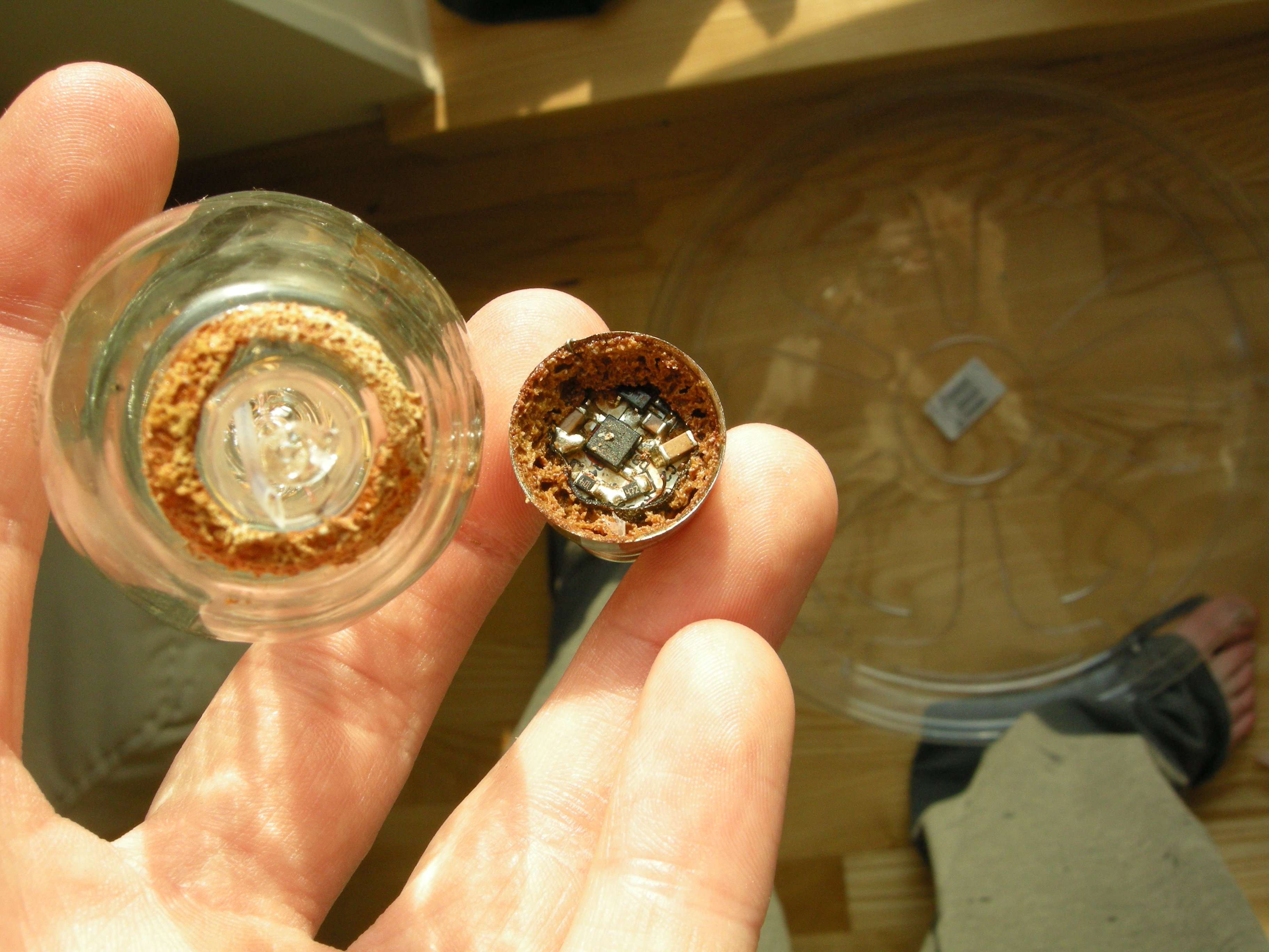
After a day-long soak in extraction gas with acetone, desoldering the b l o b b, and applying Unreasonable Force™ I finally managed to remove the bulb from this dead LED lamp!
Now if only the wires were longer than (2) shows this might be workable! fuck
Replying to @nabijaczleweli
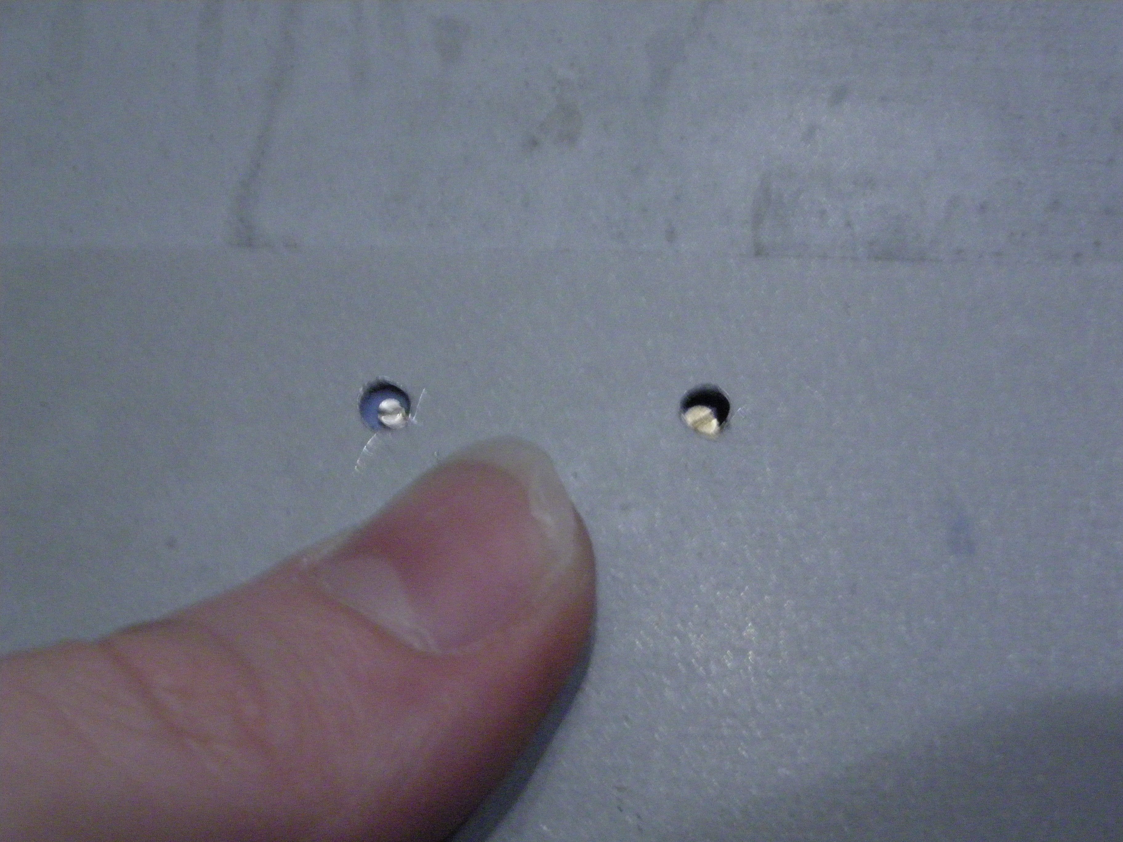
deliberately not including any photos of the setup I used to drill those because it'd give anyone with an ounce of self-preservation in their blood a heart attack
Maybe I'll just go buy a autopencil before I try do something even dumber trying to drill through this 1cm clearance
Replying to @nabijaczleweli
In a way I'm extremely lucky I don't have an access to a dremel because I would /definitely/ be missing a finger, or a bunch.
Replying to @nabijaczleweli
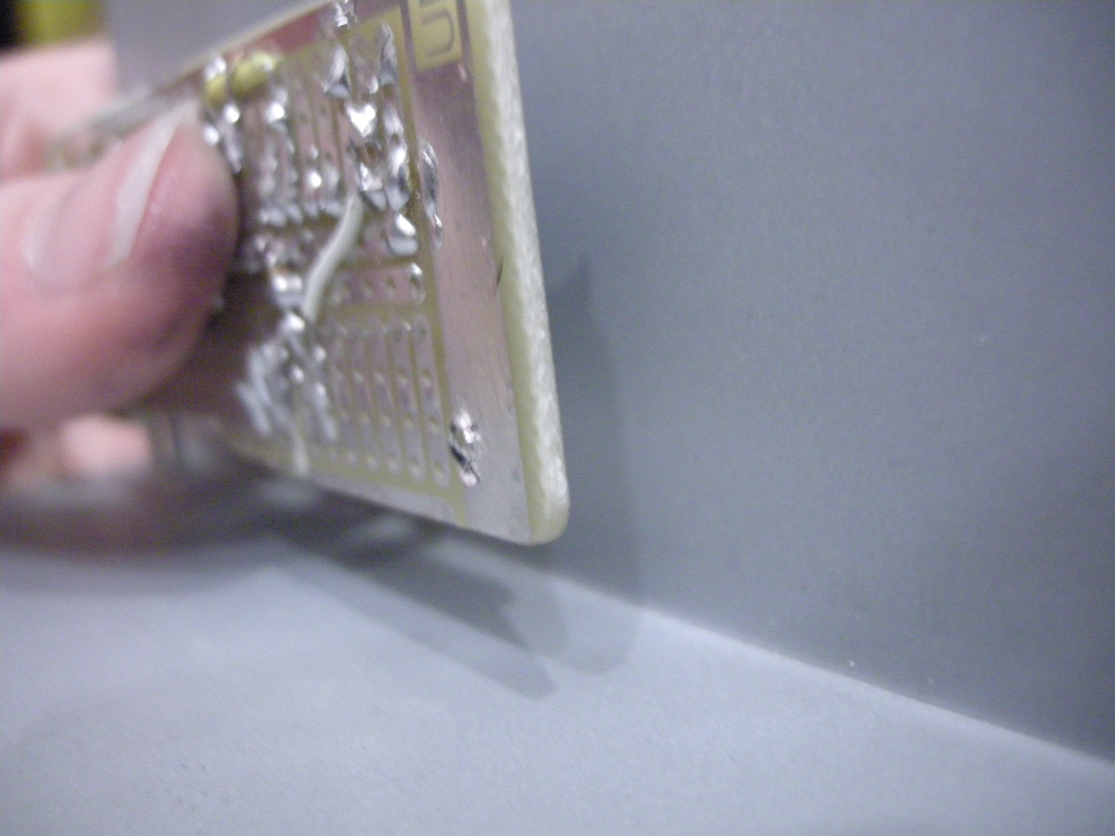
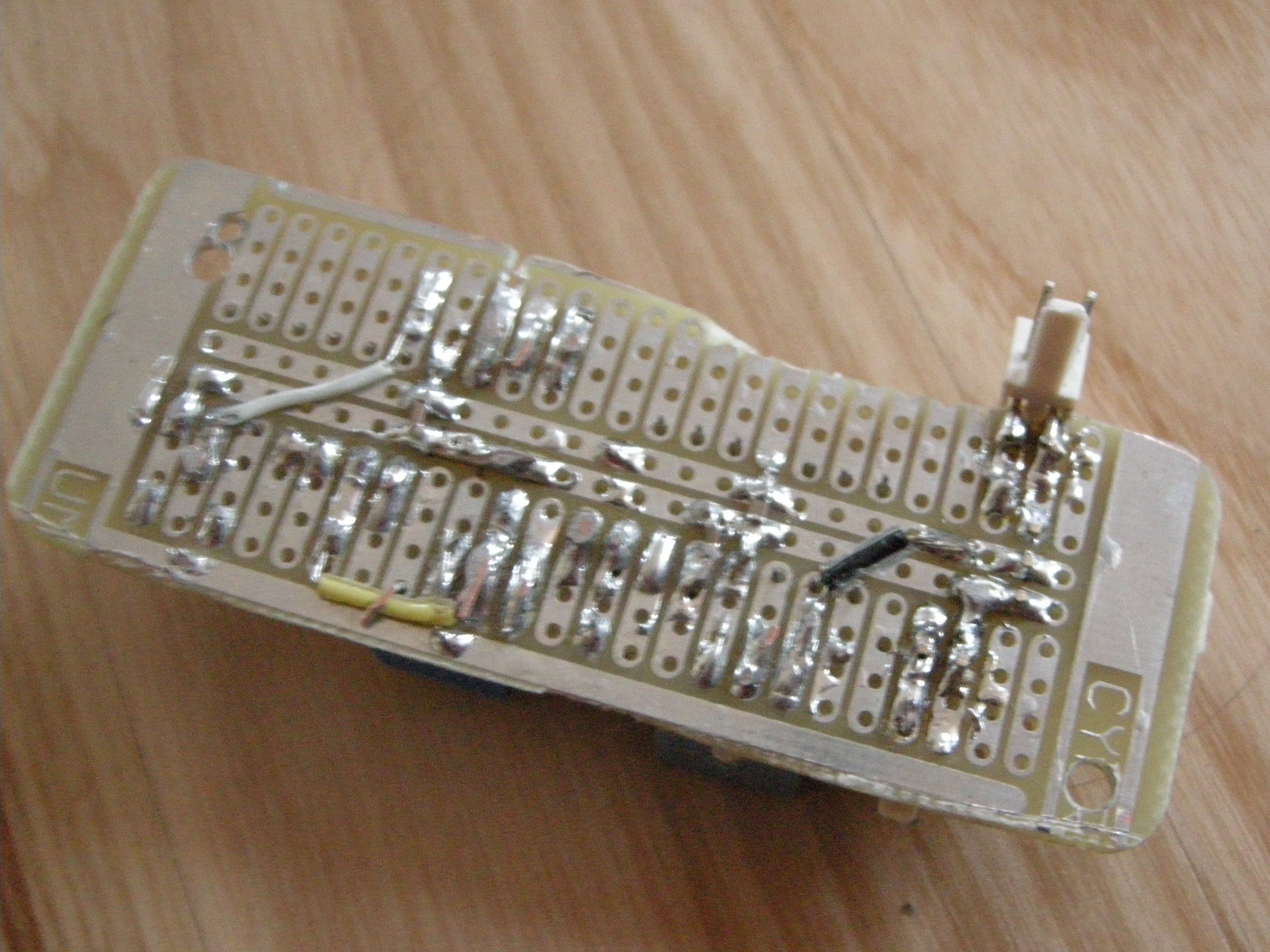
Well okay that's an exaggeration, I delammed a couple pads and the new components are a bit squint but it ~works so… progress?
Replying to @nabijaczleweli
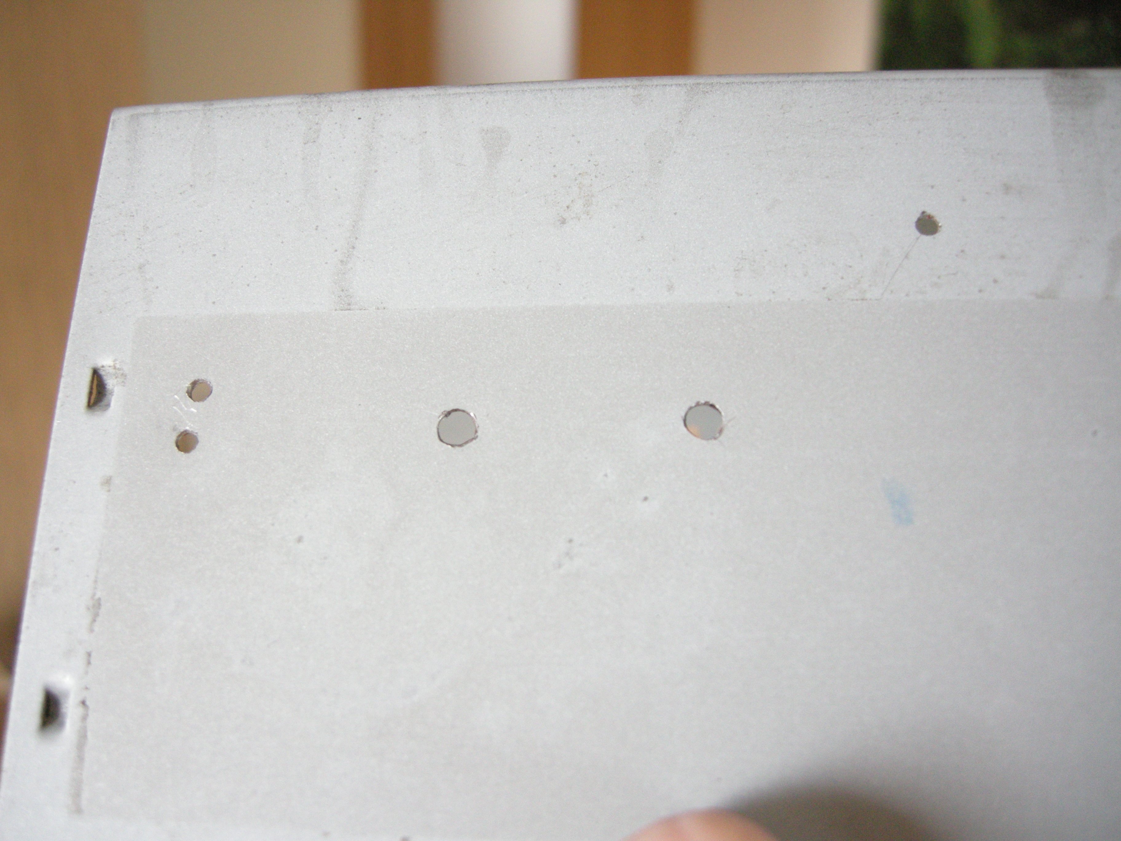
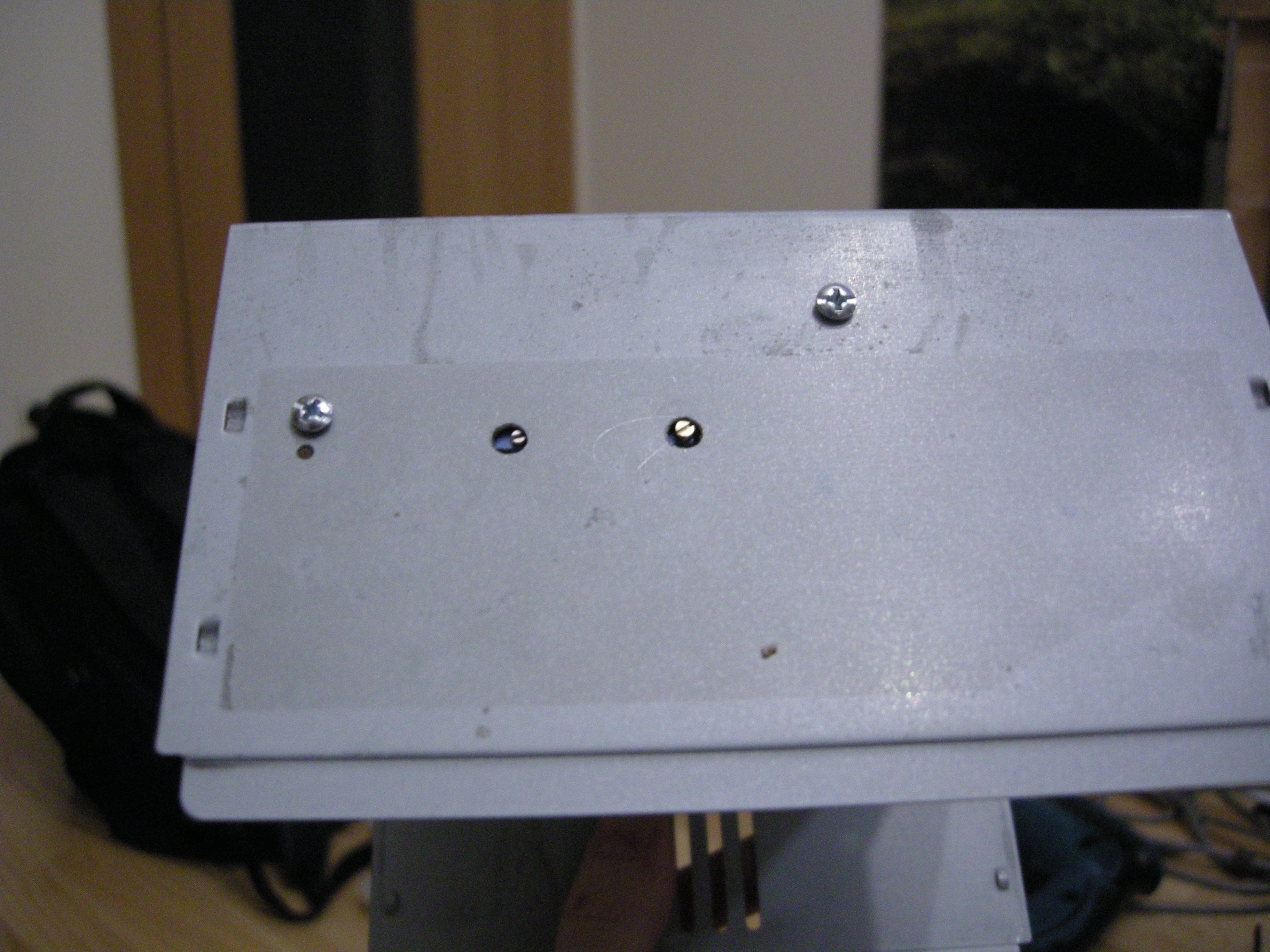
At least one of these holes should probably line up maybe
Replying to @nabijaczleweli
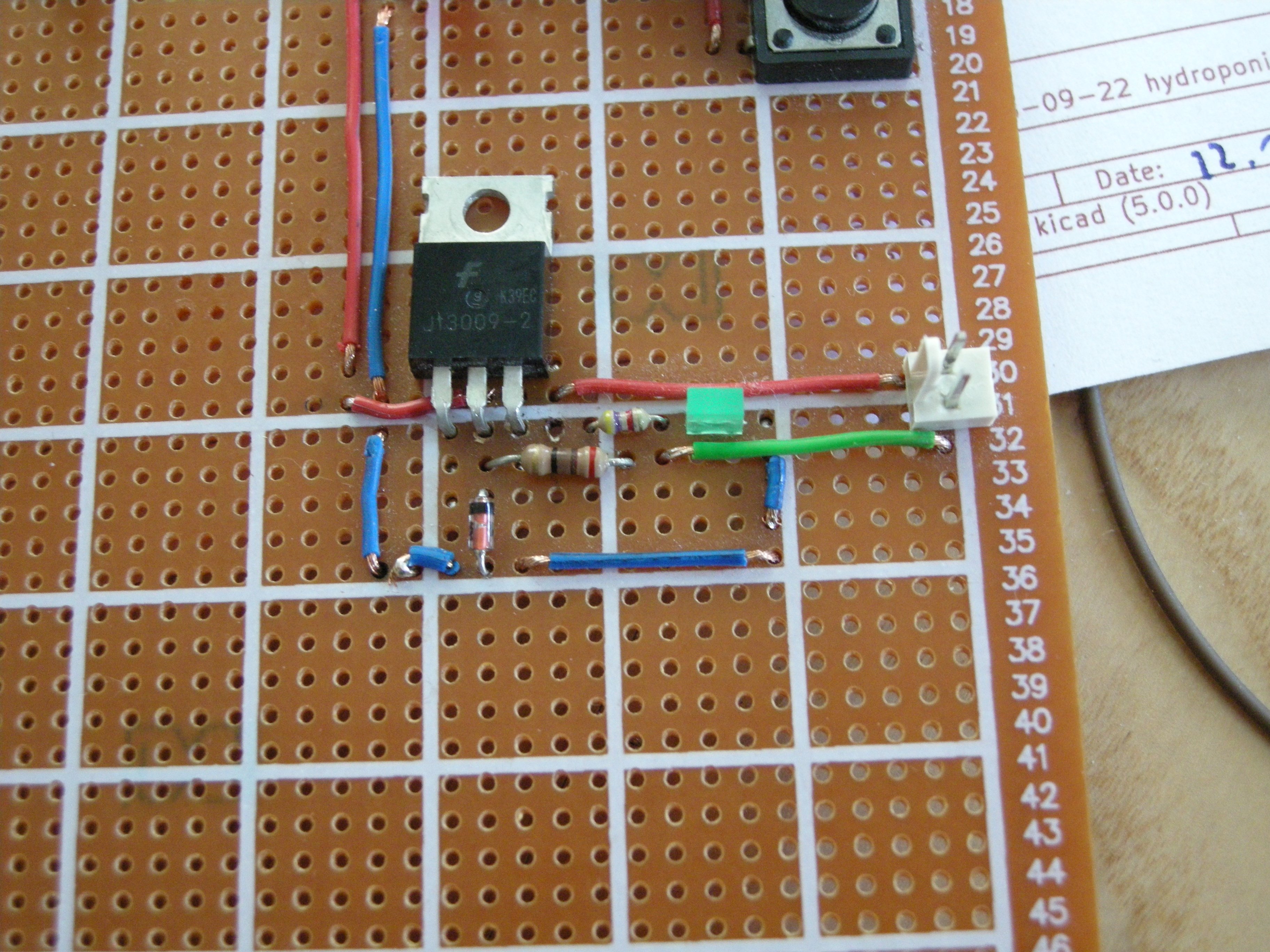
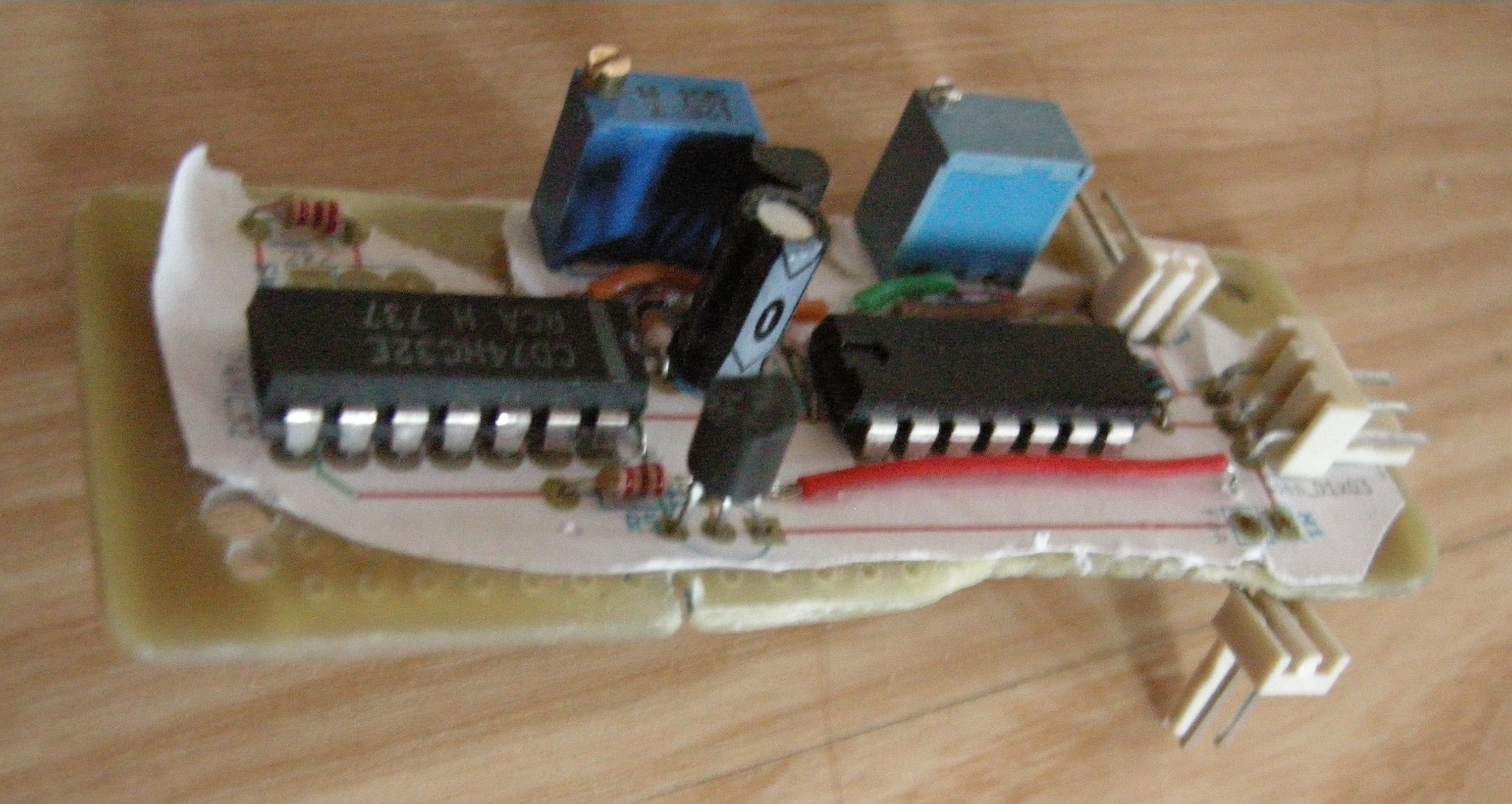
Remember to learn from your mistakes, kids! Today, to talk to you about fixing your trash designs, we've invited R11, the forthleading expert in not blowing transistors!
Replying to @nabijaczleweli
Finally found some scissors (harder than expected tbh), cut the wires, and oh god it's even worse inside, what kind of resin(?) is this, it looks like rotting flesh help
Replying to @ClarisRobyn

Replying to @nabijaczleweli
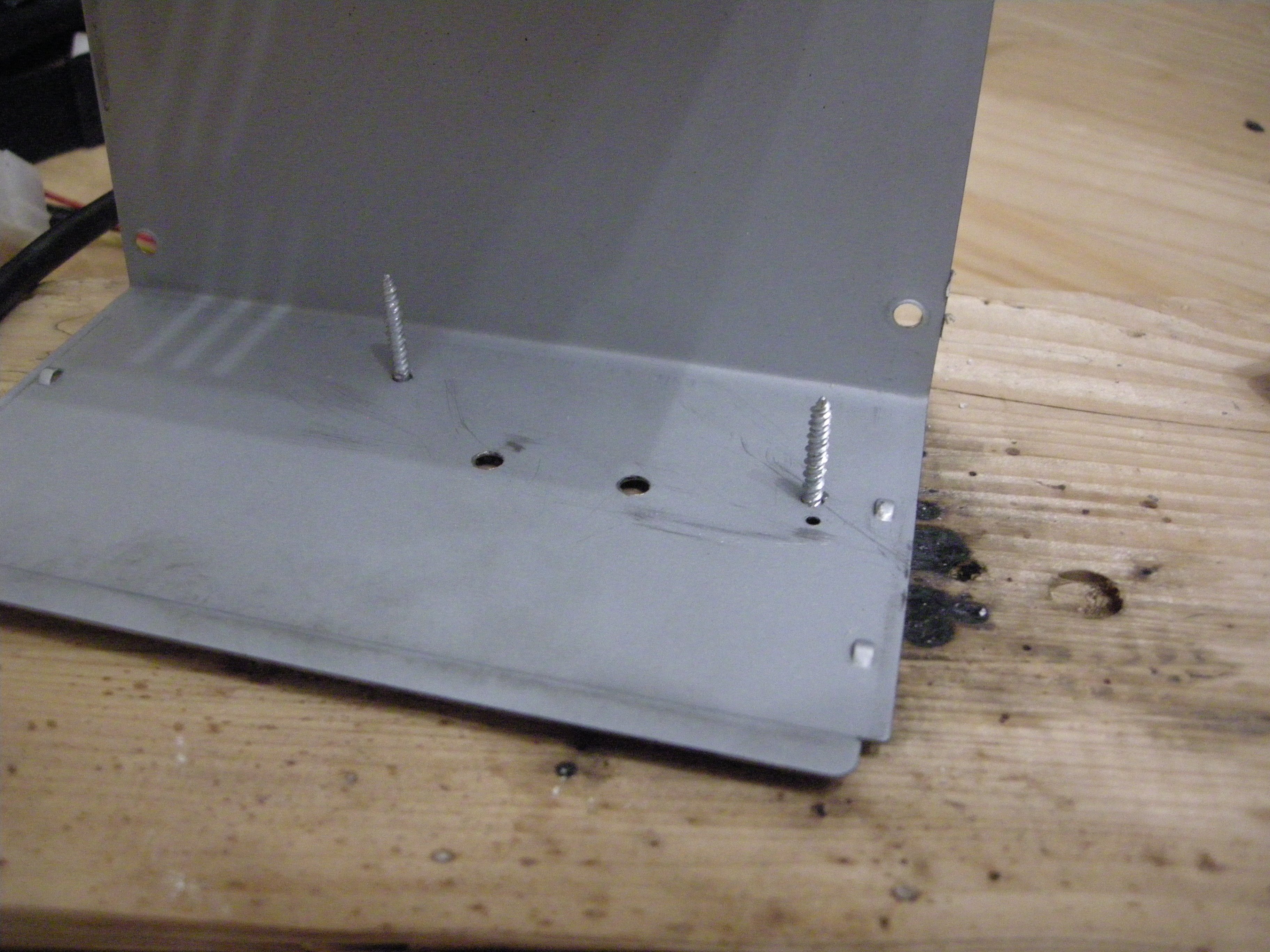
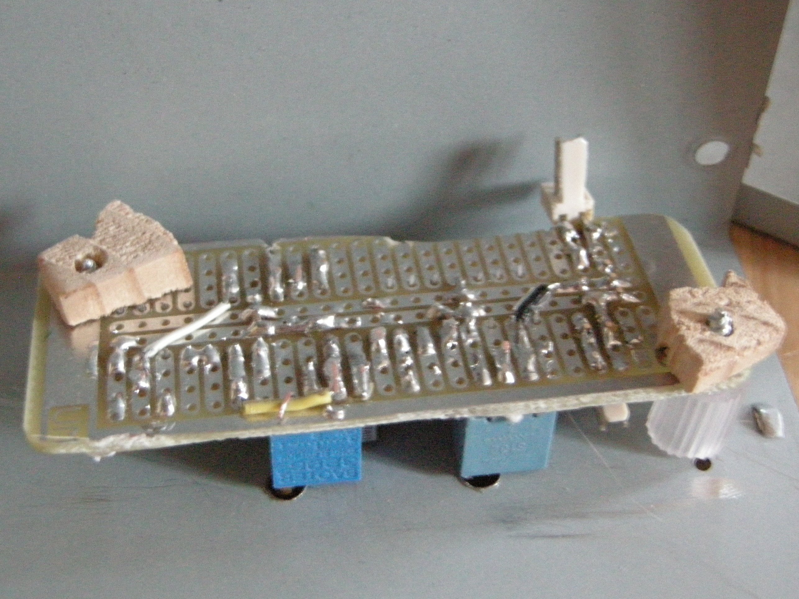
A further bit of drilling and not stabbing my hand later, we have:
* screws, going through a
* silicone tube because that's what I'd, meeting with the
* circuit board, and topped off with
* some cut-offs from the Quite Dodgy Drawer https://twitter.com/nabijaczleweli/status/1046888590721126401, laying 'round


Replying to @nabijaczleweli
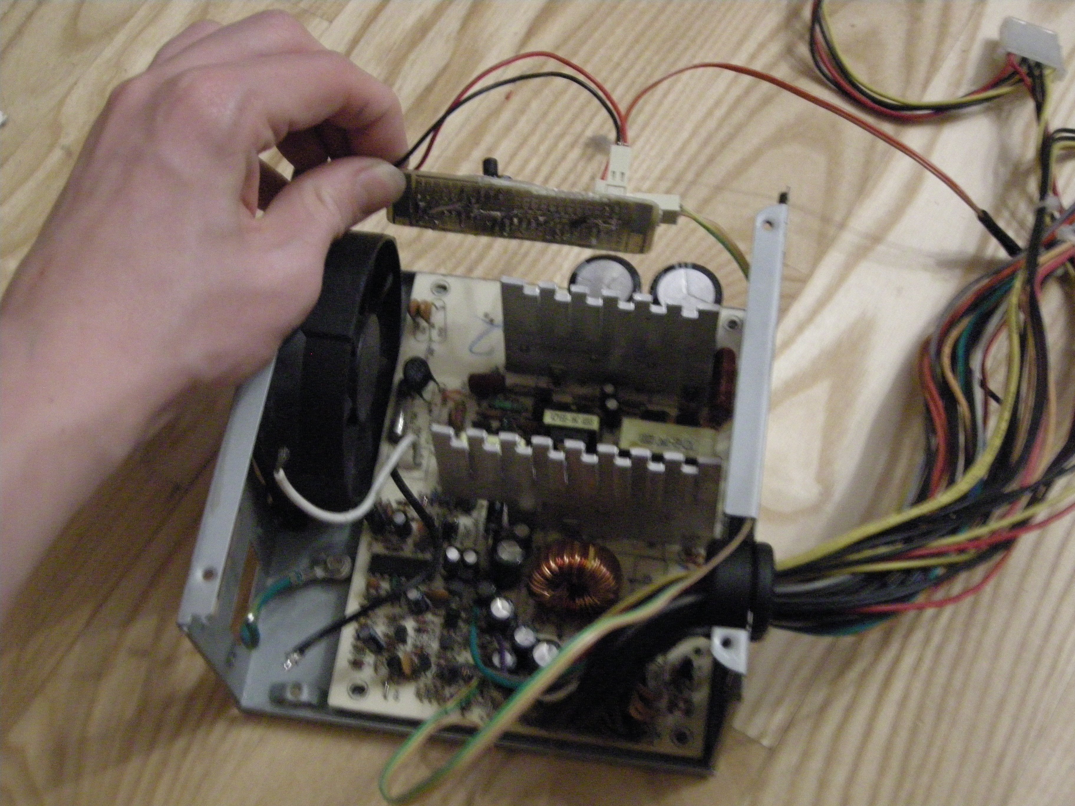
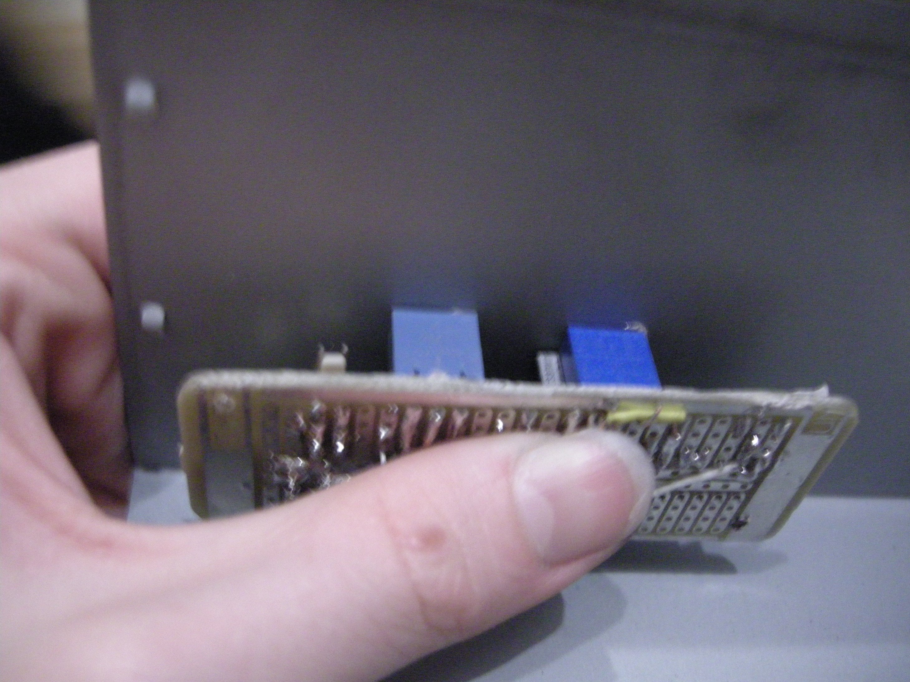
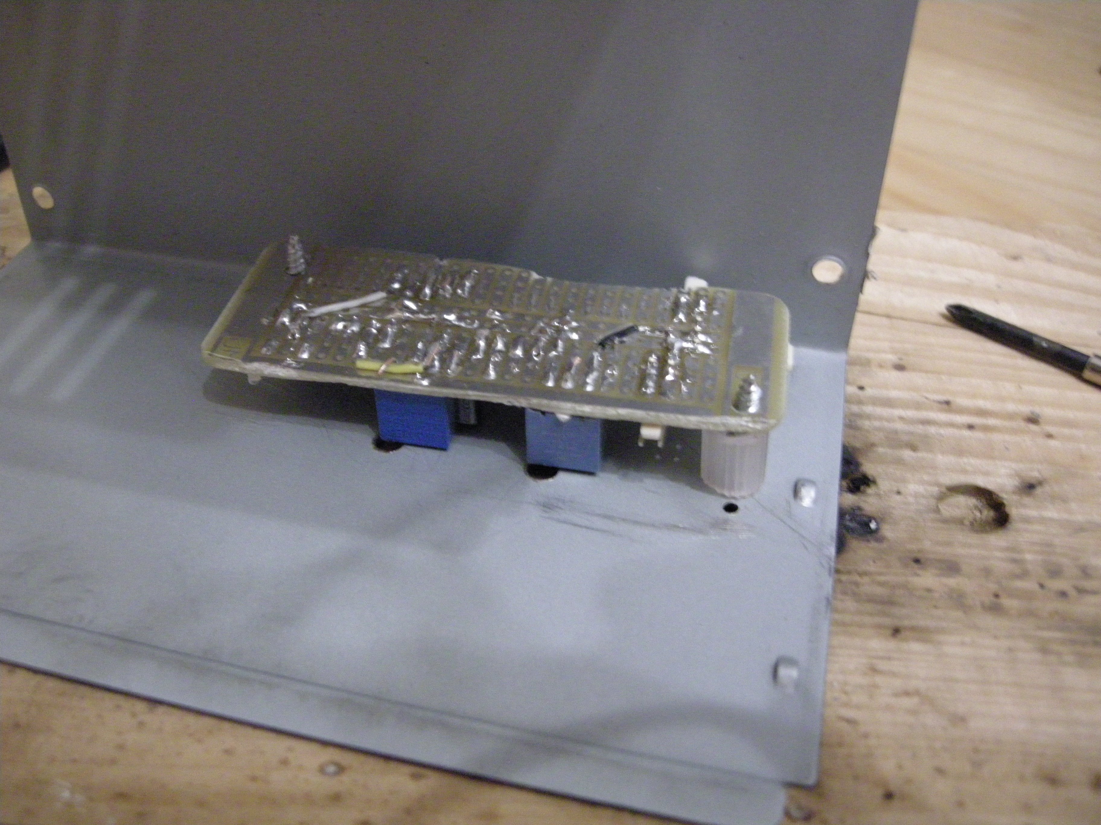
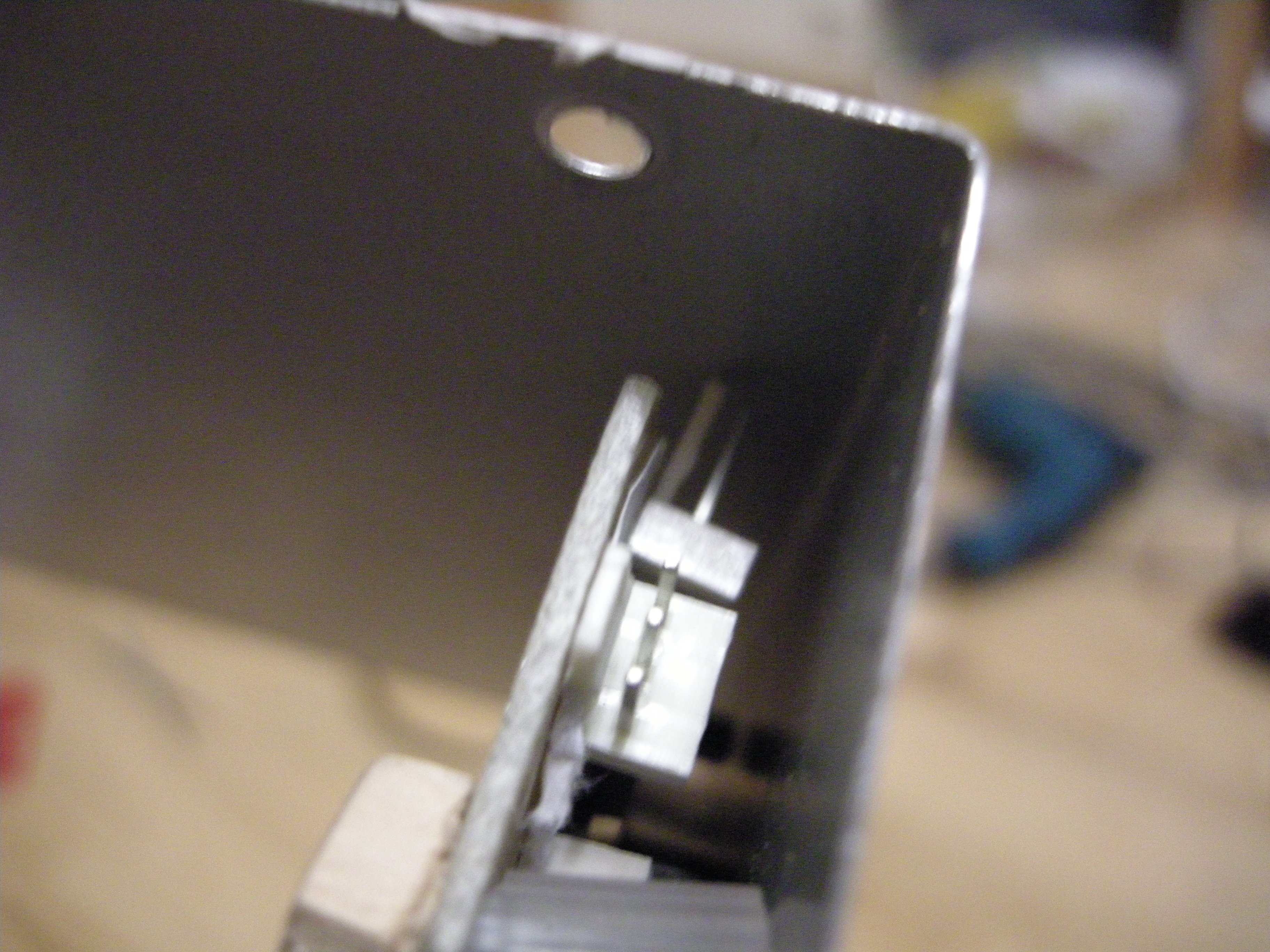
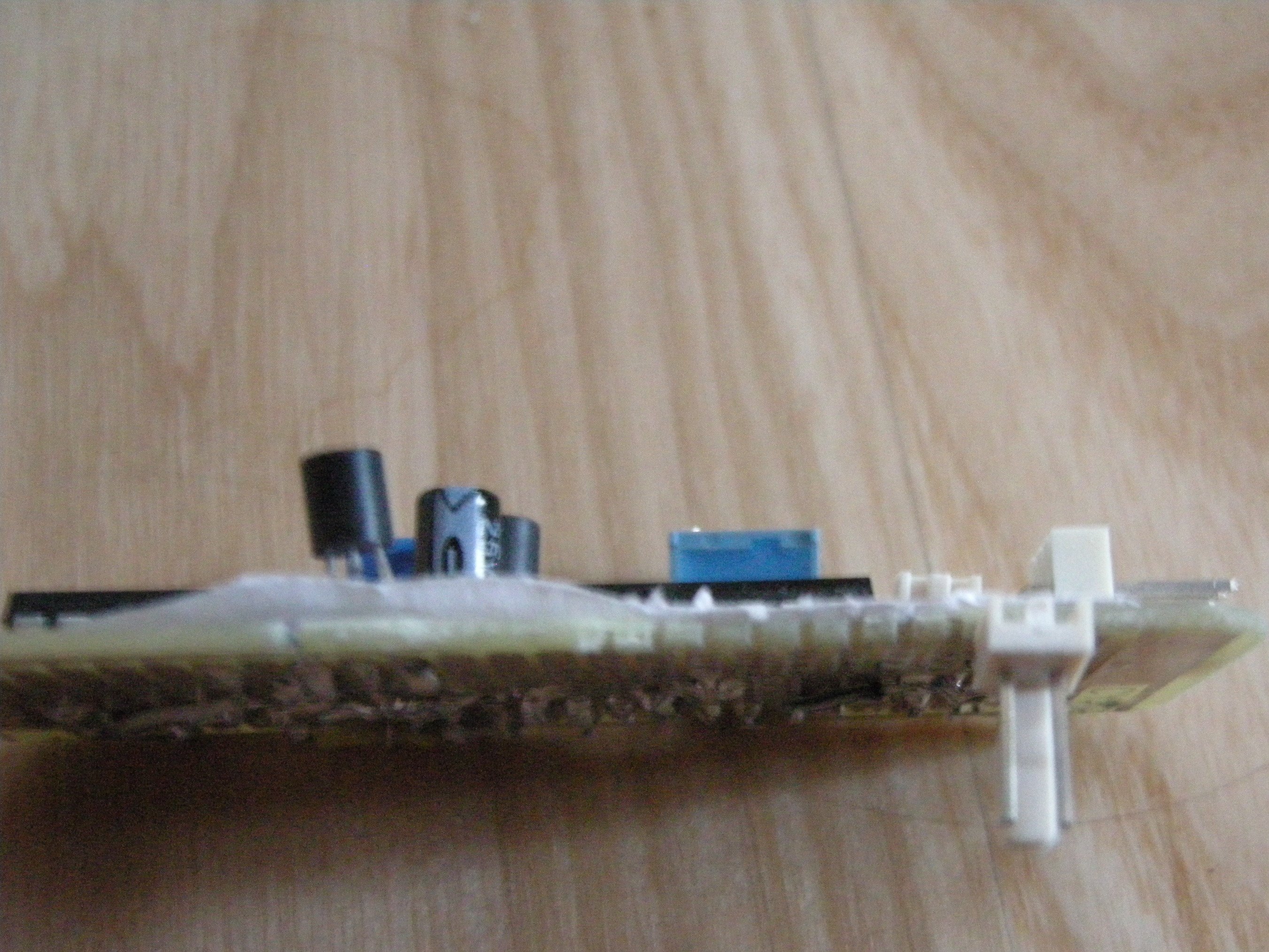
Now! This all looks cool and good and all, but there's literally zero damned clearance between the fan connector and the case, which is, indeed, very cool
Starting to think my "drill first, ask questions never" approach might be flawed
Replying to @nabijaczleweli
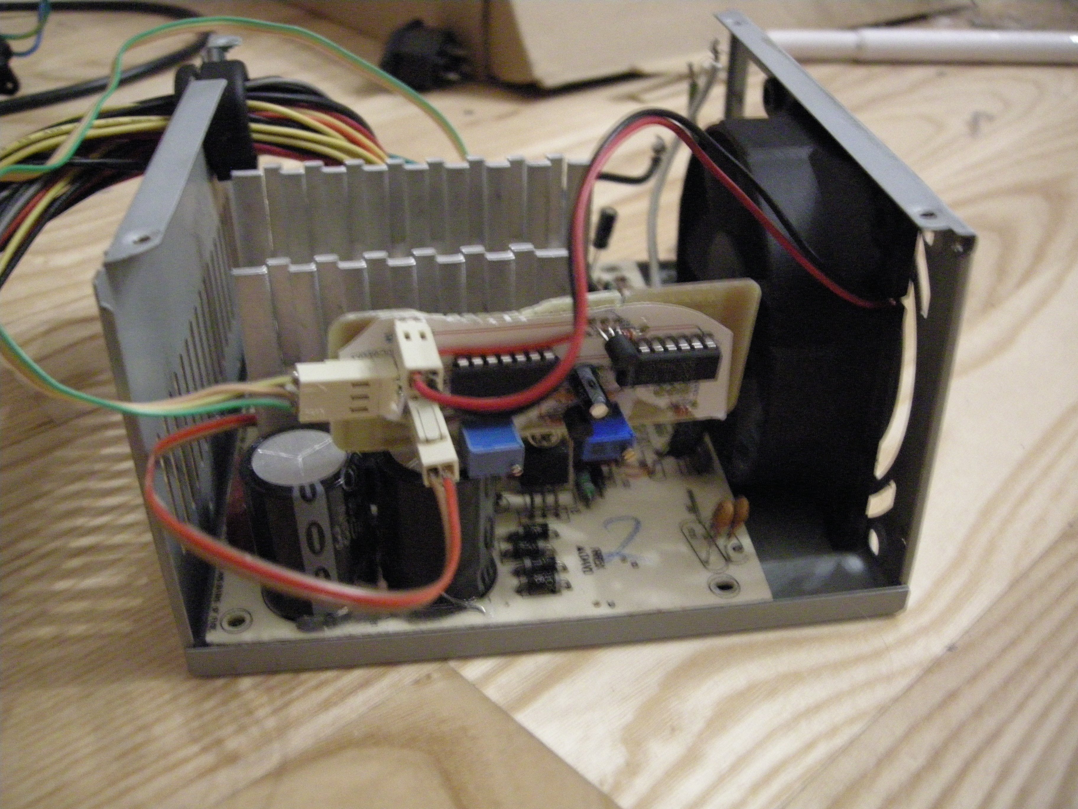
on the other hand I just realised I can resolder the connector to the copper side and so what's the point of designing anything if you can just fix it in production ?
Replying to @nabijaczleweli
an another absolute revelation that just hit me is that I could've just used normal panel-mountable potentiometer if I'd more than two active brain cells but
Replying to @nabijaczleweli
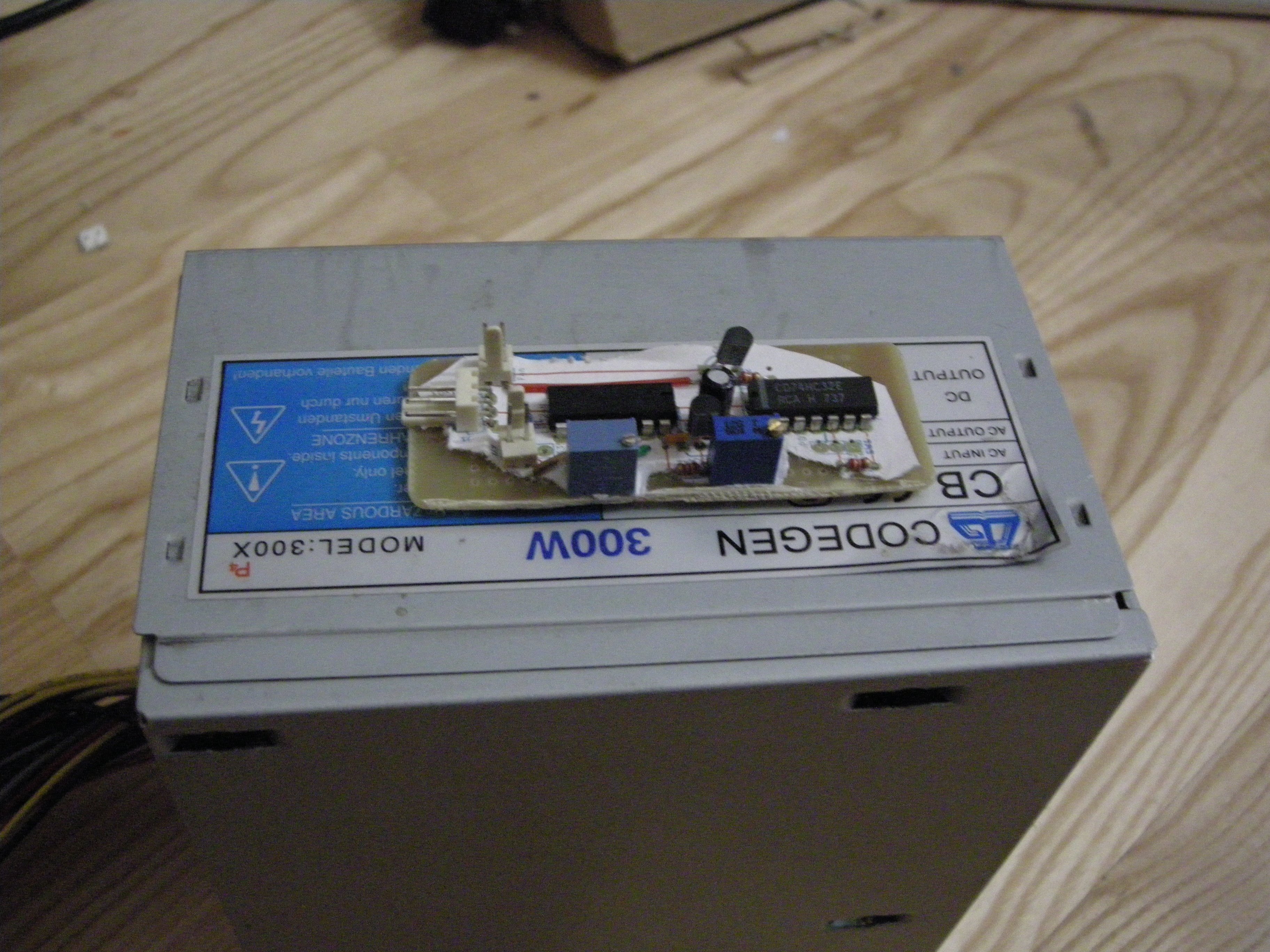
And so, mind triumphs over being a dumbass once more!
Replying to @nabijaczleweli
The timestamps say 4:55am so I believe them, despite failure to recall any part of the process


Replying to @PancakeIdentity and @Vazkii
I mean . . that's kinda the goal innit
how the hell ?..
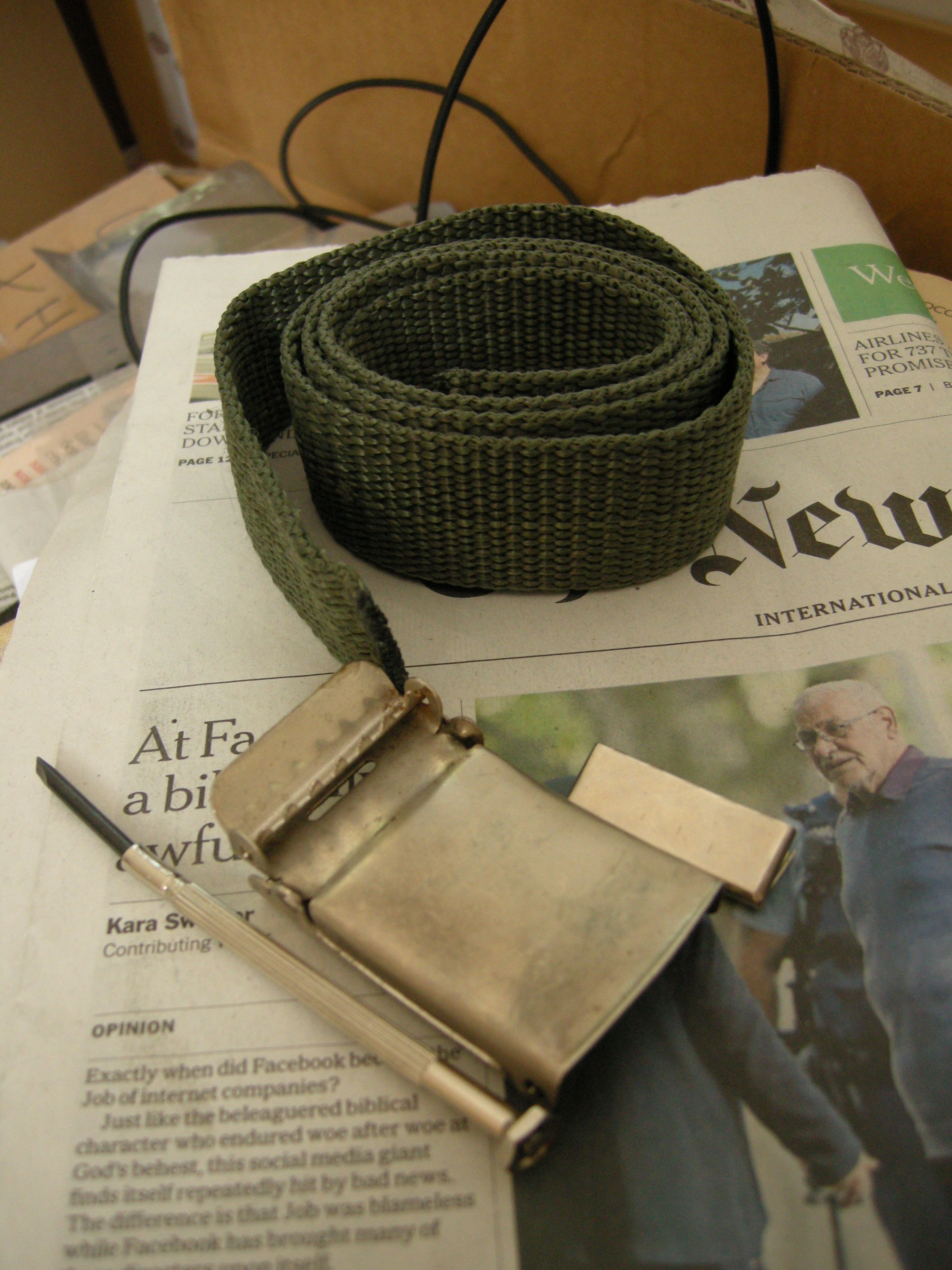
came across this old belt when cleaning and hmmmmmmmmmm

Replying to @nabijaczleweli
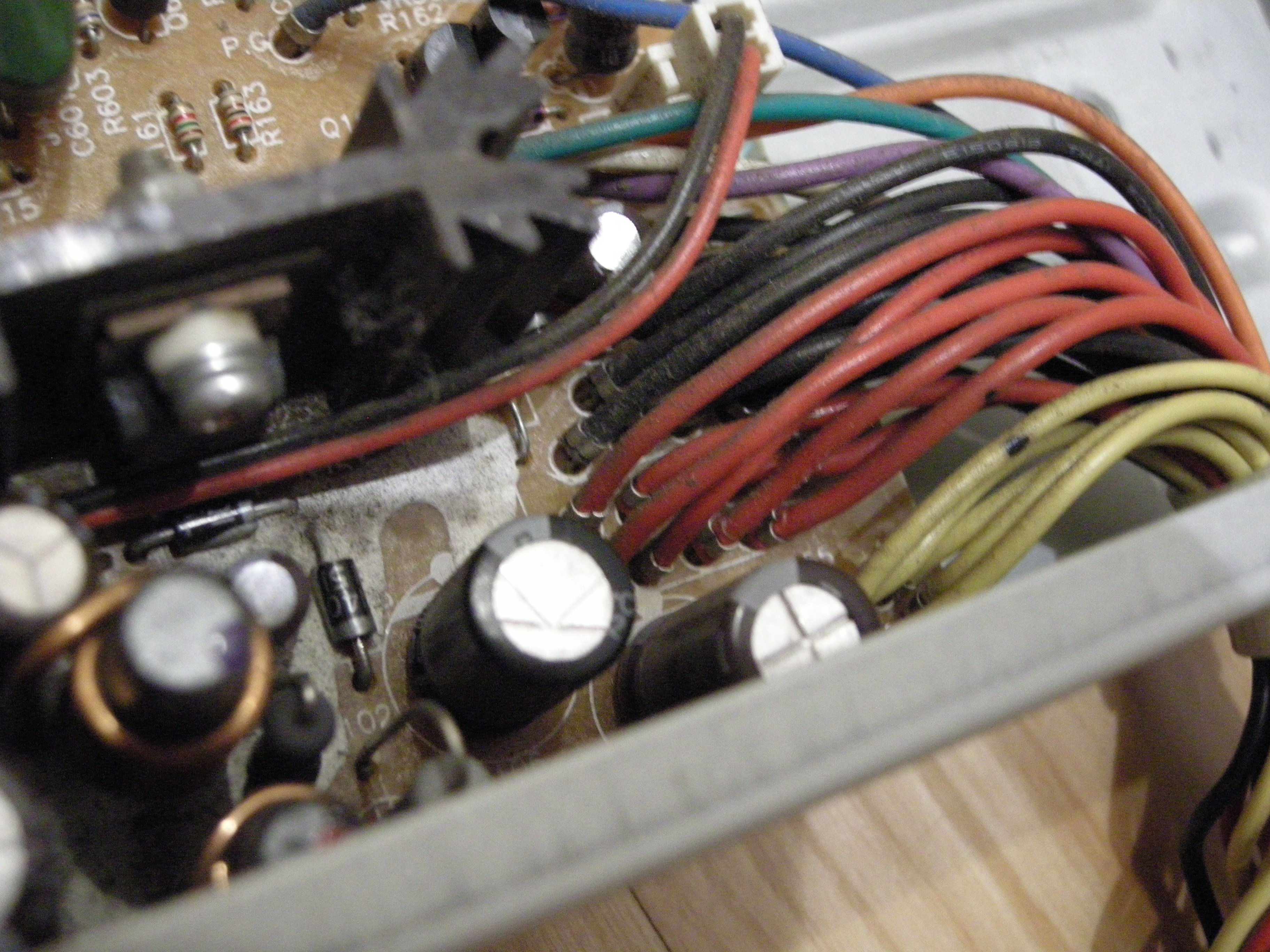
More aleae were iacted, output delay sexion in place (this transistor is also shorted internally for what I assume is some very good reason)
Replying to @nabijaczleweli
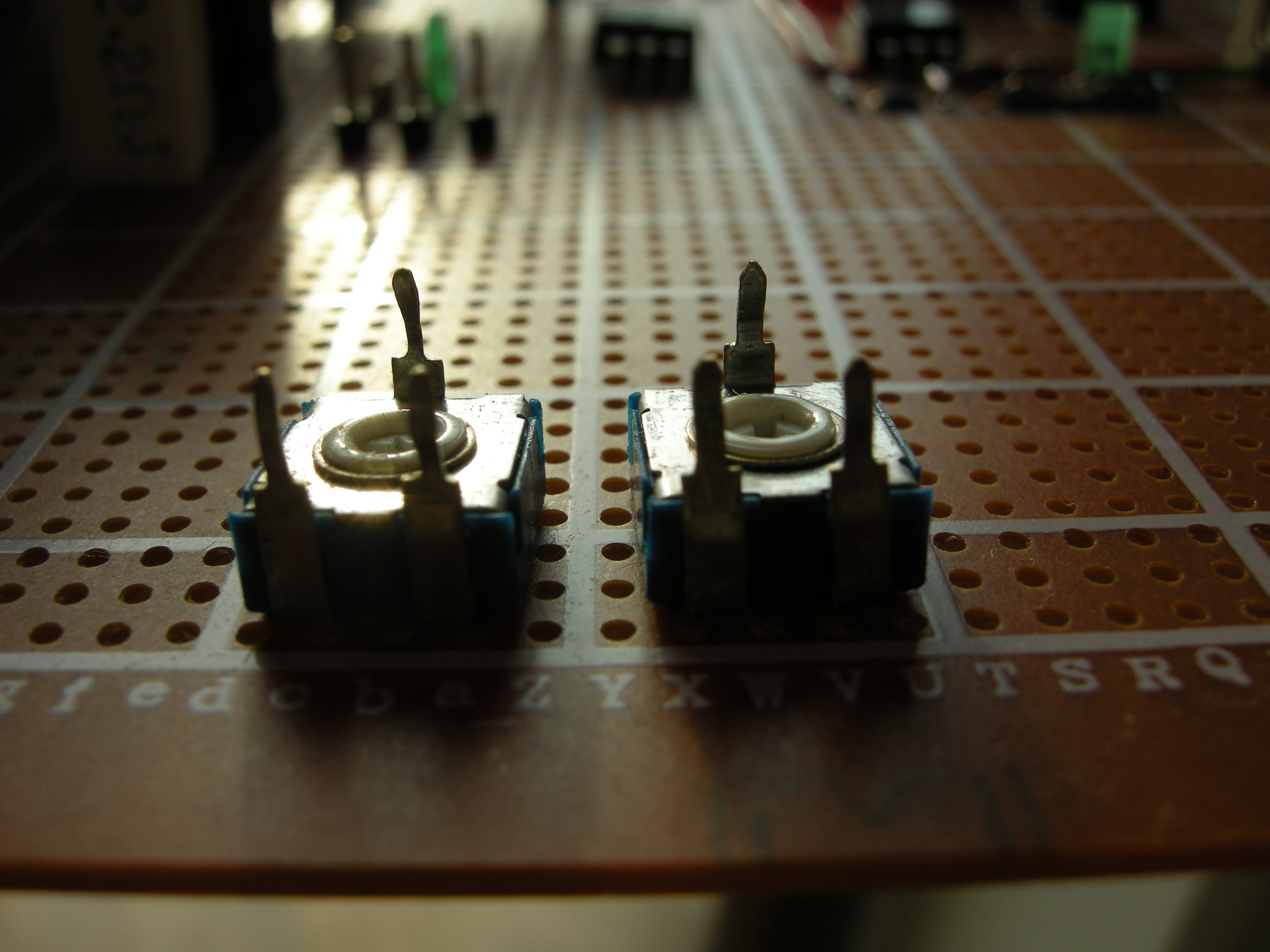
Includes a hand-filed potentiometer, because these never fit anywhere and are a general pain in the arse
Replying to @nabijaczleweli
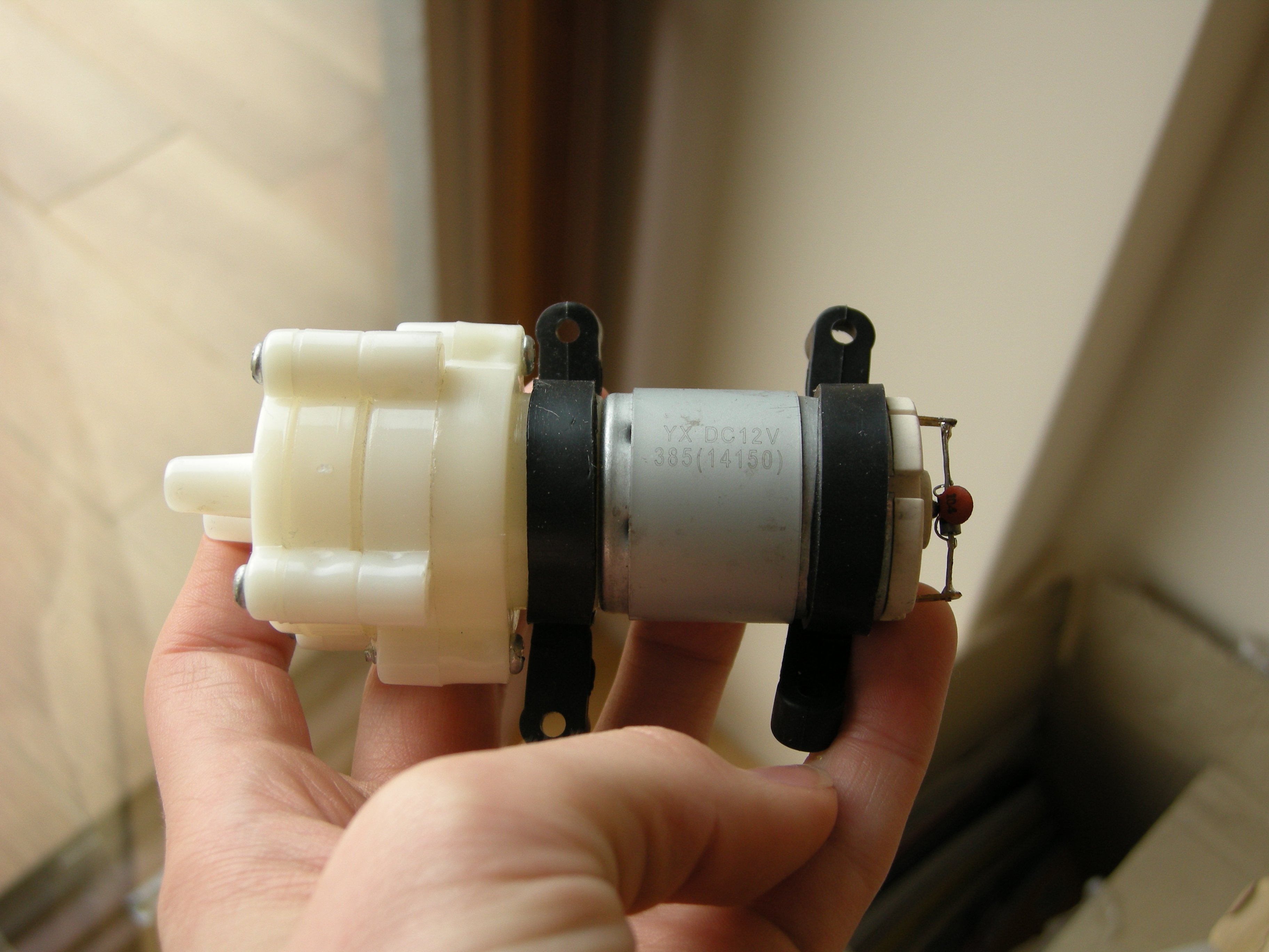
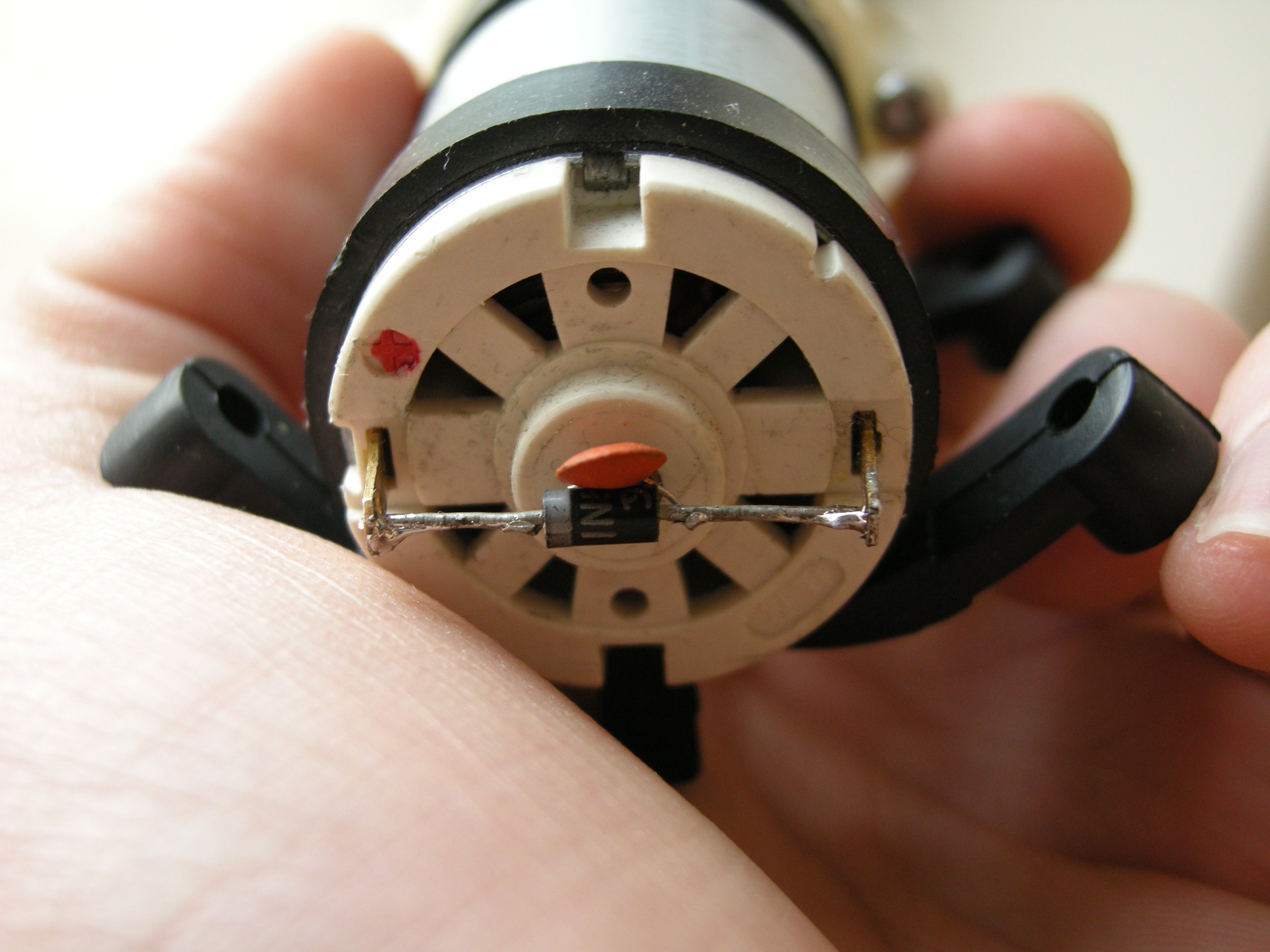
Snubber network for the pump, pulled back a little afterward, so the motor shaft doesn't grind through the diode package hopefully
Not sure if it's the camera or Soviet technical thought but I'm having a real big-time trouble focusing down my old детский микроскоп nowadays :/
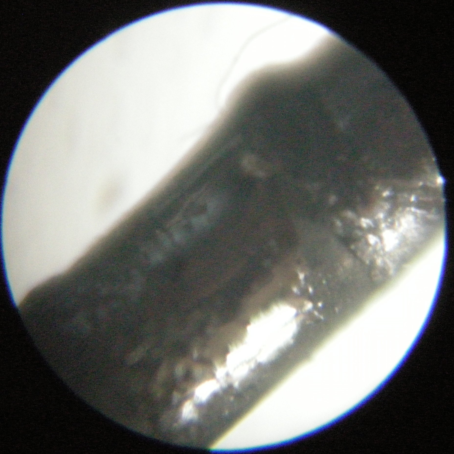
Replying to @greenTetrah
sweet spot
Replying to @nabijaczleweli
That went much easier than I'd thought!
Replying to @nabijaczleweli
dunno what the professional way of doing this is but my soldering iron's gay now, so that's a win in-of itself

Replying to @nabijaczleweli
к р ё м п

Replying to @nabijaczleweli
This tape is both narrower (an inch vs 3cm) and thinner, so I'm only getting a relatively good grip when doubled-back, but still
yeee-haw, pardner

fifteen minutes in ?

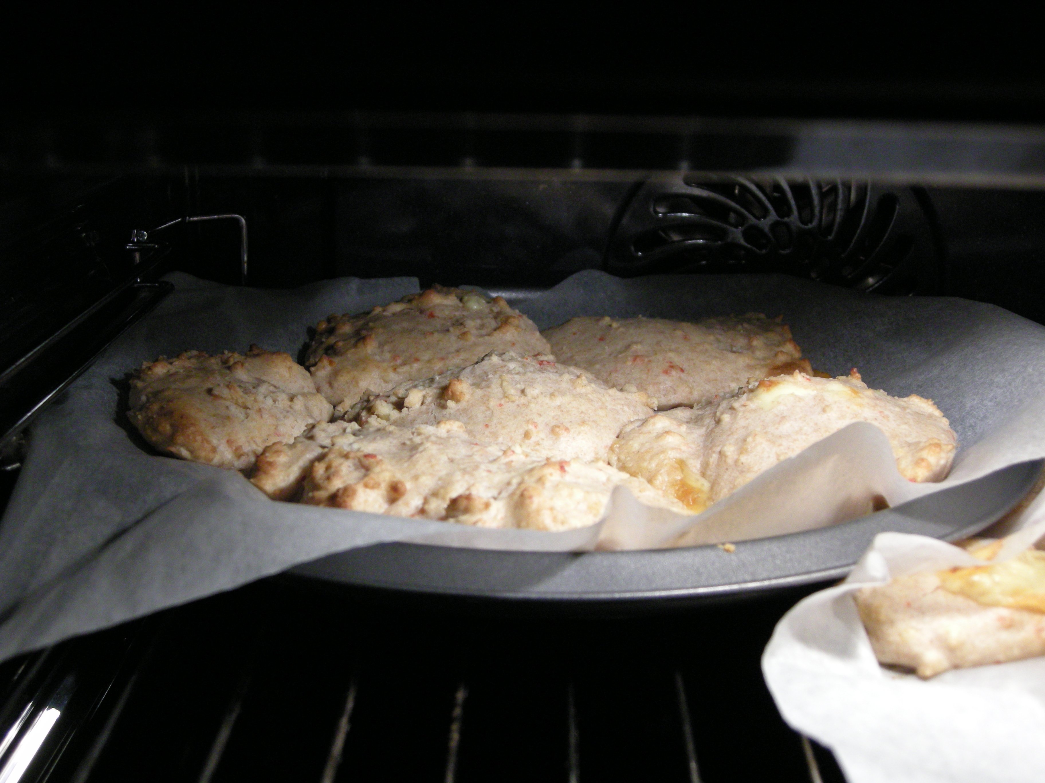

Replying to @nabijaczleweli
another ten, goodness knows what this is, but it's edible! so


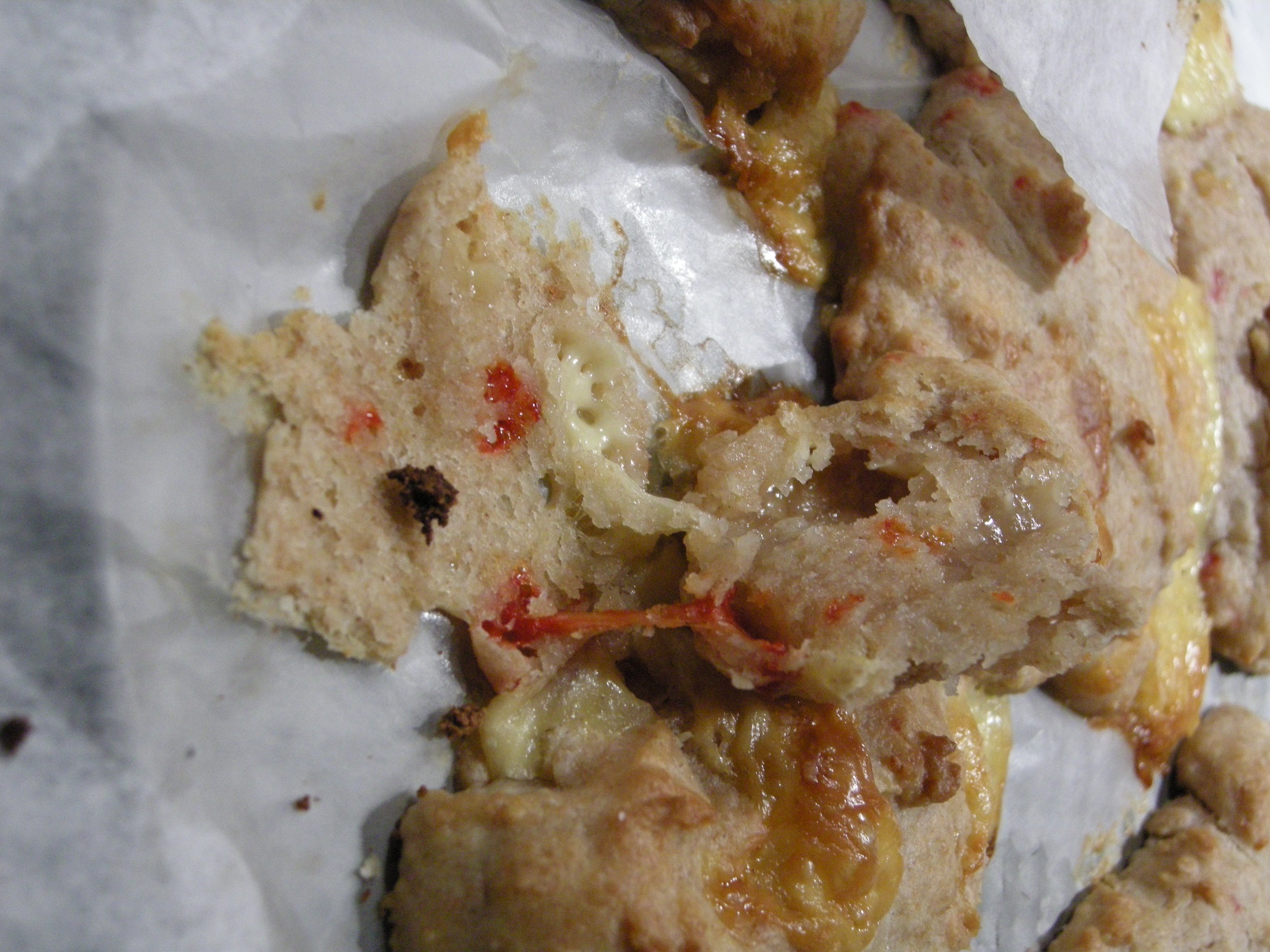
Technically finished high school?
Replying to @nabijaczleweli
l o m g friend !
Replying to @PLT_cheater
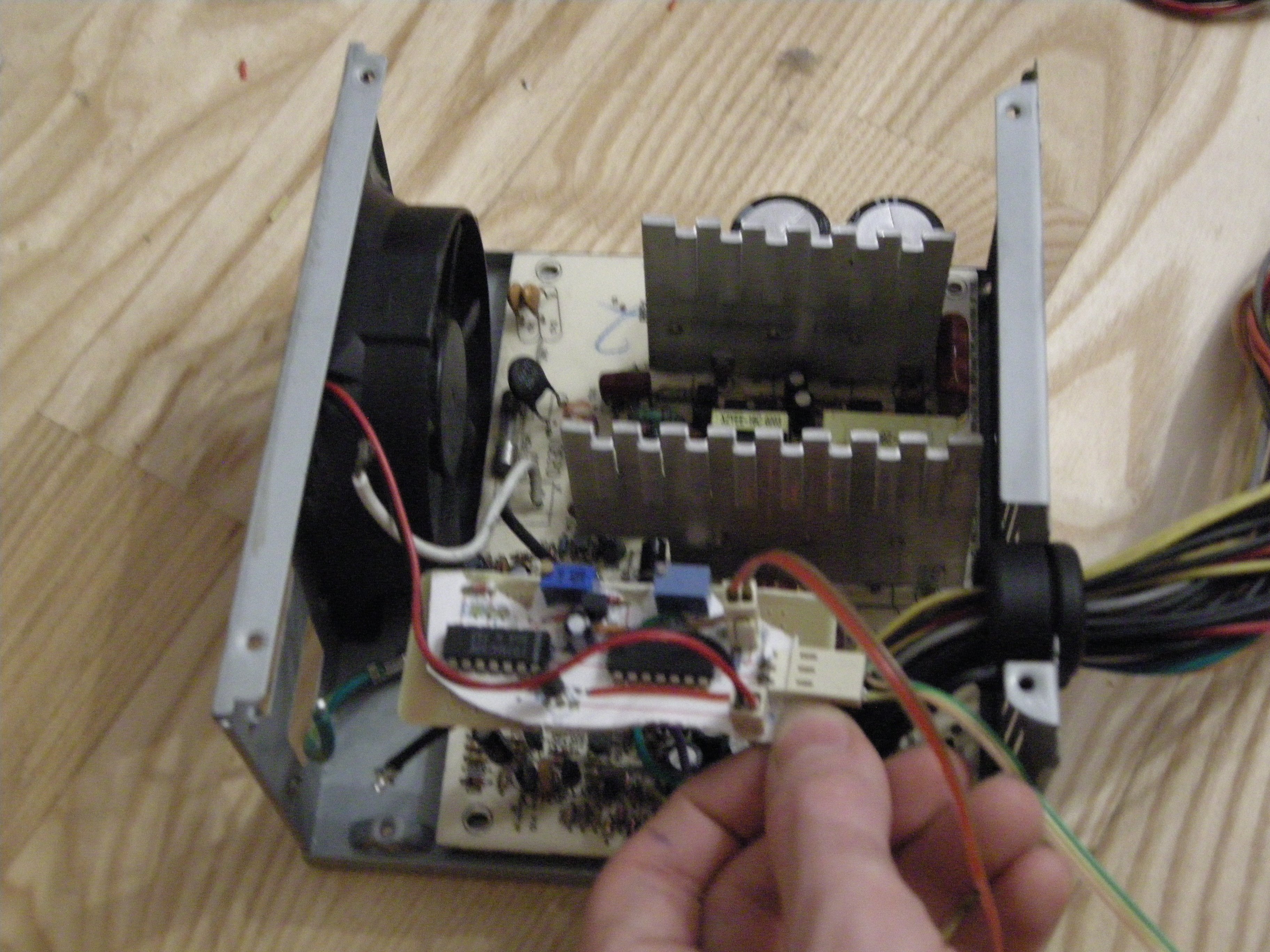
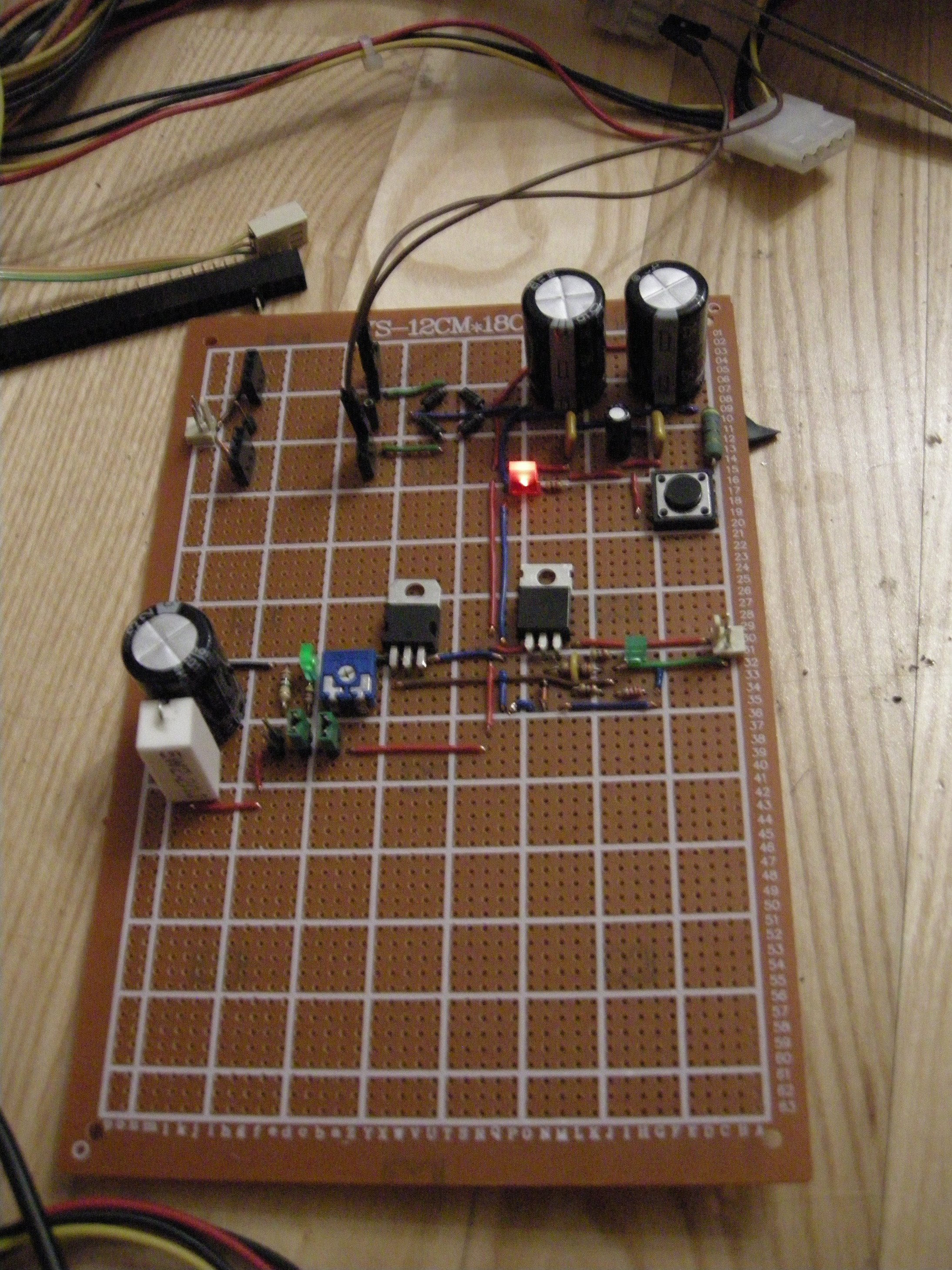
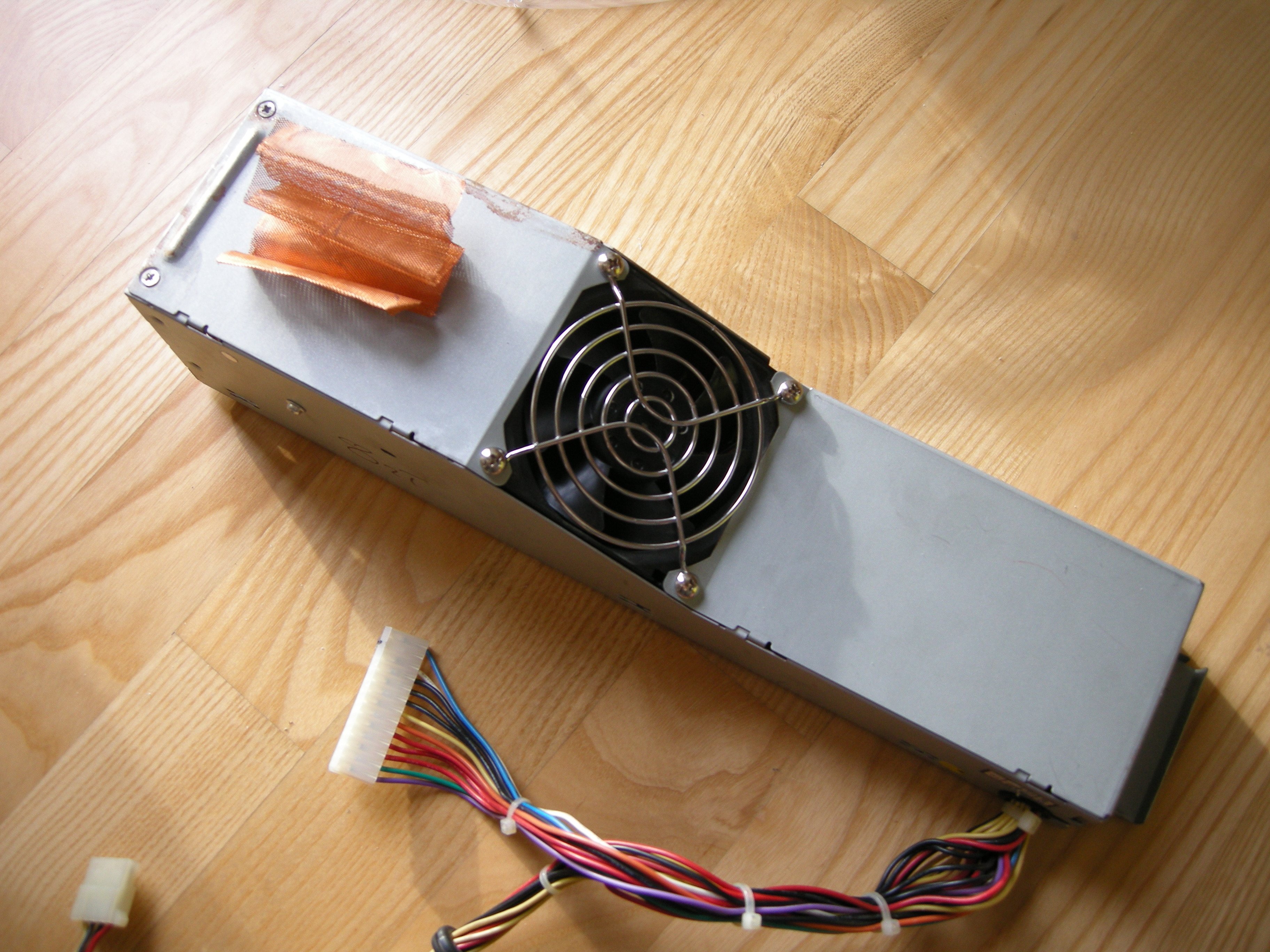
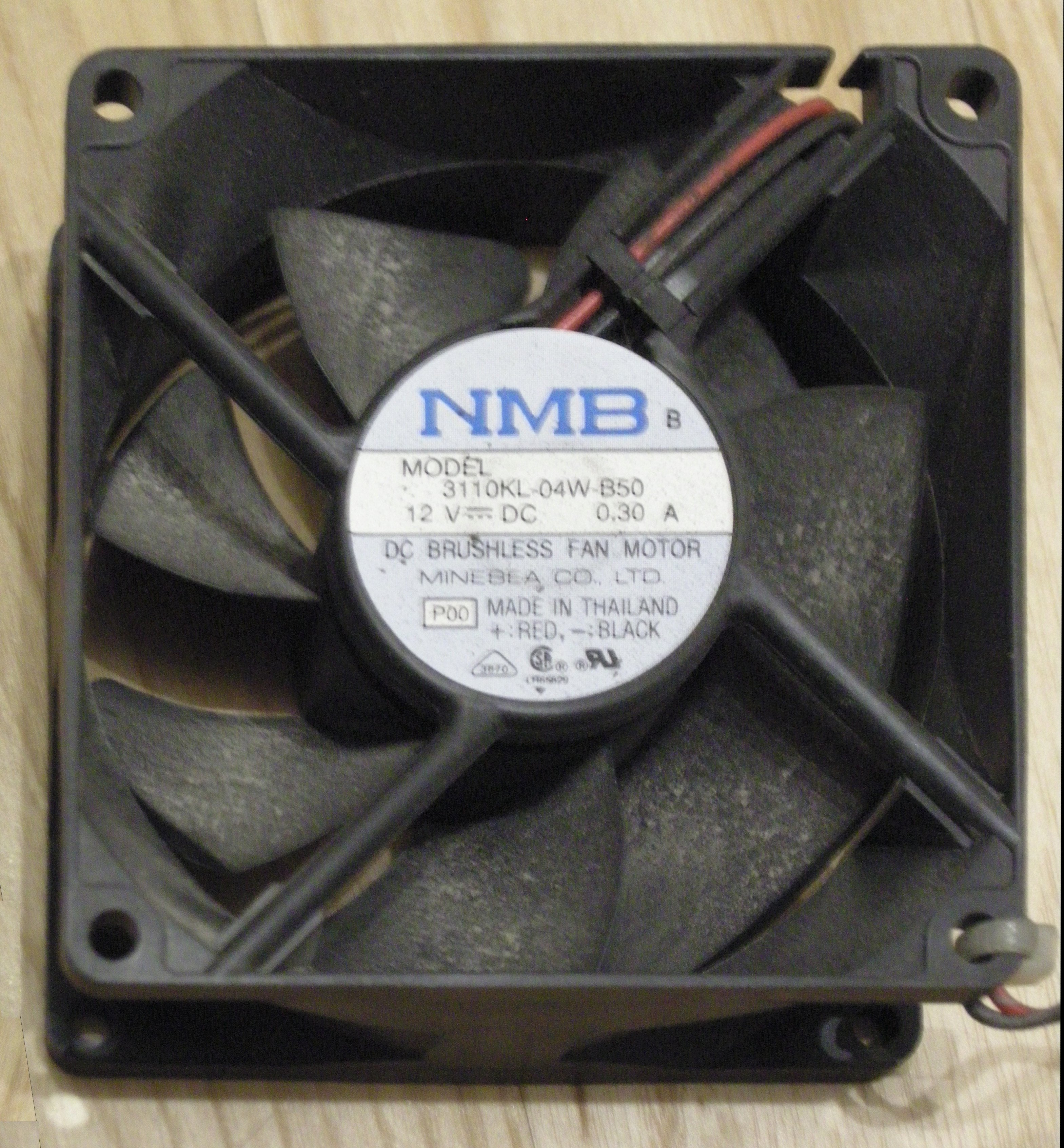
an overengineered attempt at A Thing that only turns on the case fan of this ATX PSU when the heatsink reaches a pre-set temperature because it's too noisy to've it running all the time !
Replying to @PLT_cheater
sounds expensive and quite susceptible to parallax, what with measuring the temperature of the fan vs that of the heatsink (also thermocouples scare me, as a concept), as opposed to what is essentially a 1-2 dollar-equivalents' worth of jellybeans tbh
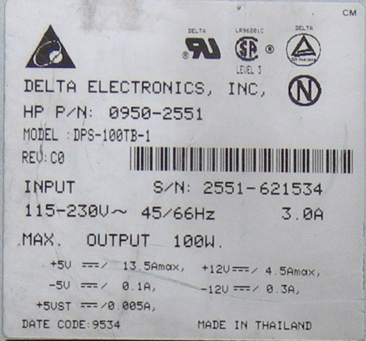
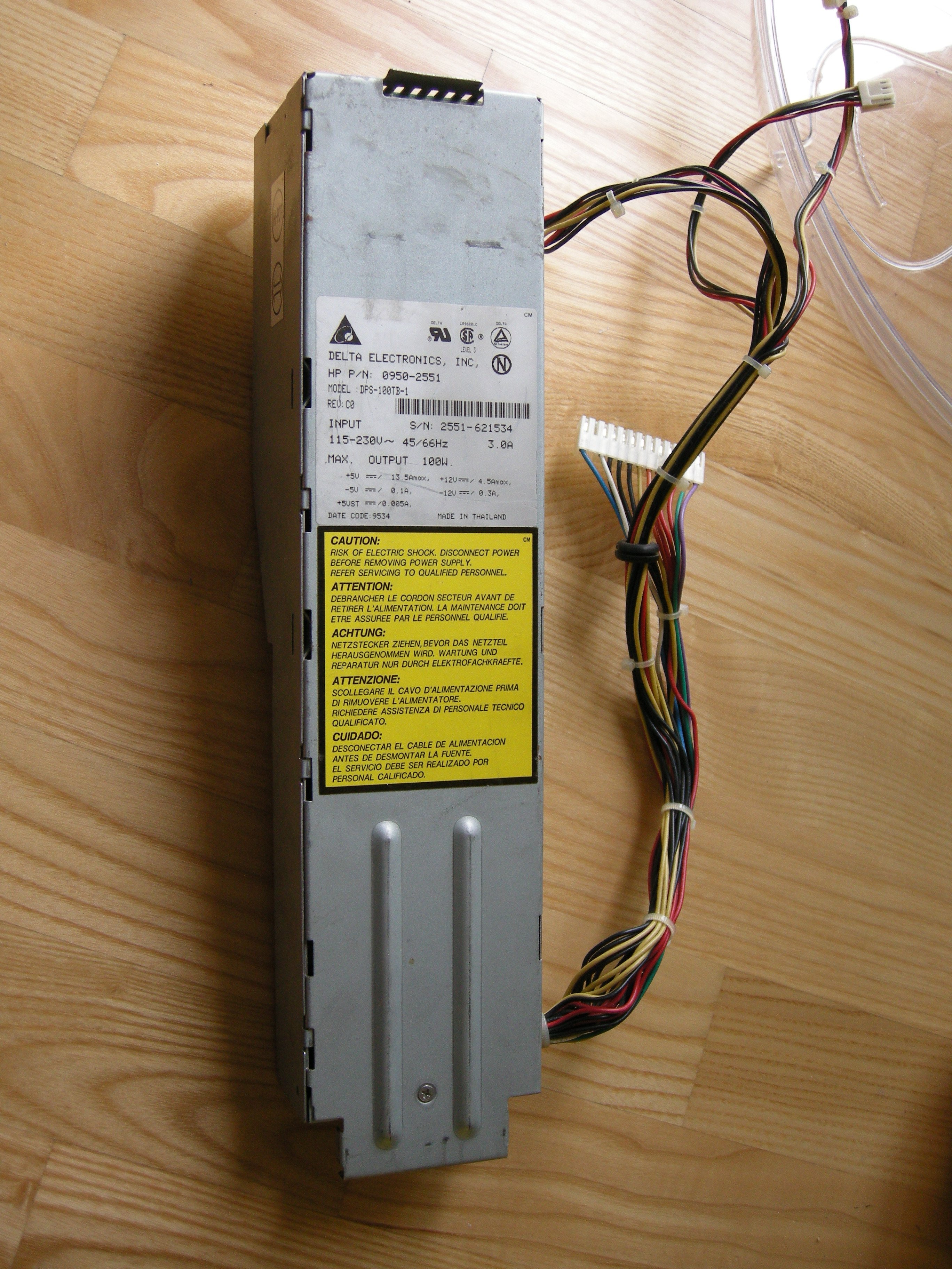
the lad down at the shop said he tried to bring this absolute beast of a pardner (en theorie holds 125.625 nameplates, says it's limited to 100) to life, but also that he couldn't get it to chooch, so here it is, on my floor, asking for… 115 to 230V at 45 or 66 Hertz? hmmmm
Replying to @PLT_cheater
two euros… on top of a fourty euro (cheapest I could find in the right form factor from papst @ a local distributor, not incl. shipping) fan… would make it cost eighteen times as much as the PSU in-of itself…
Replying to @PLT_cheater
I don't think I /have/ fourty-two euros plus shipping to my name rn ?
Replying to @PLT_cheater
from my tests so far, running it on temperature trip for a good dozen seconds is ~good enough~, so vive l'ingenierie
Replying to @UsualHotDog
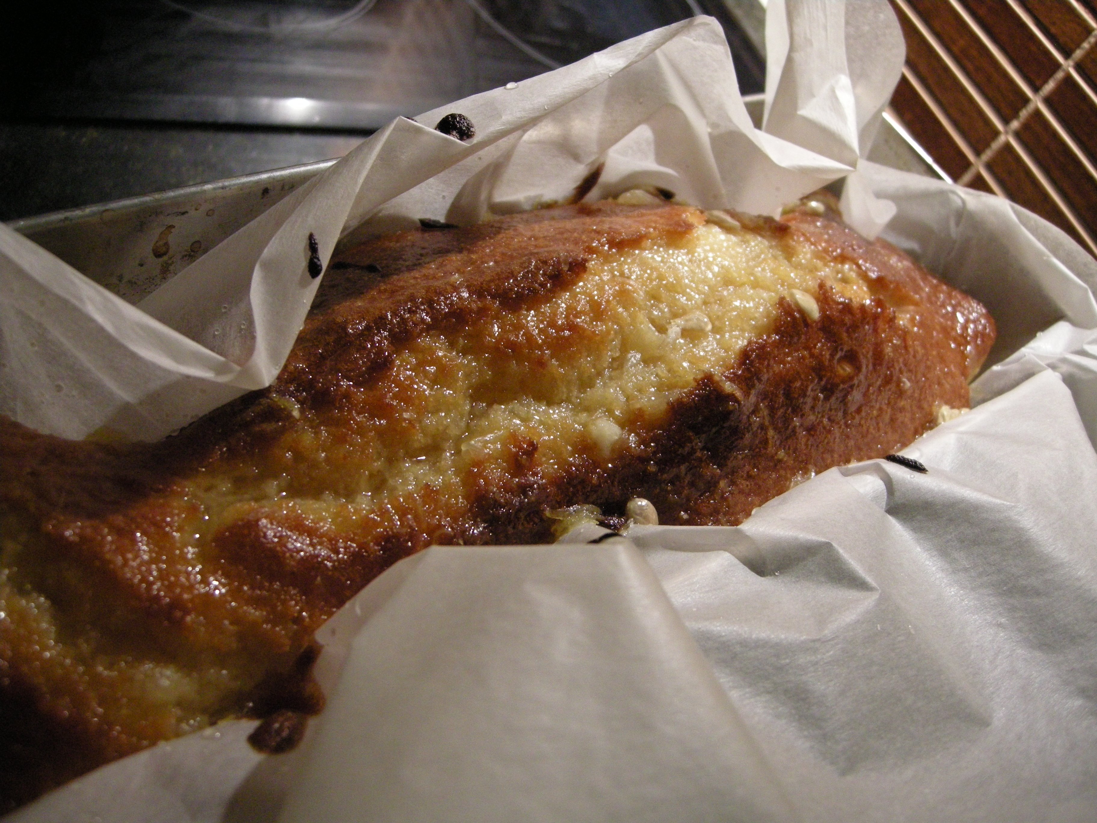
mmmhmmm 🍞 bringin' 🍞🍞 dem 🍞🍞🍞 loaves 🍞🍞🍞🍞 baby
Replying to @nabijaczleweli
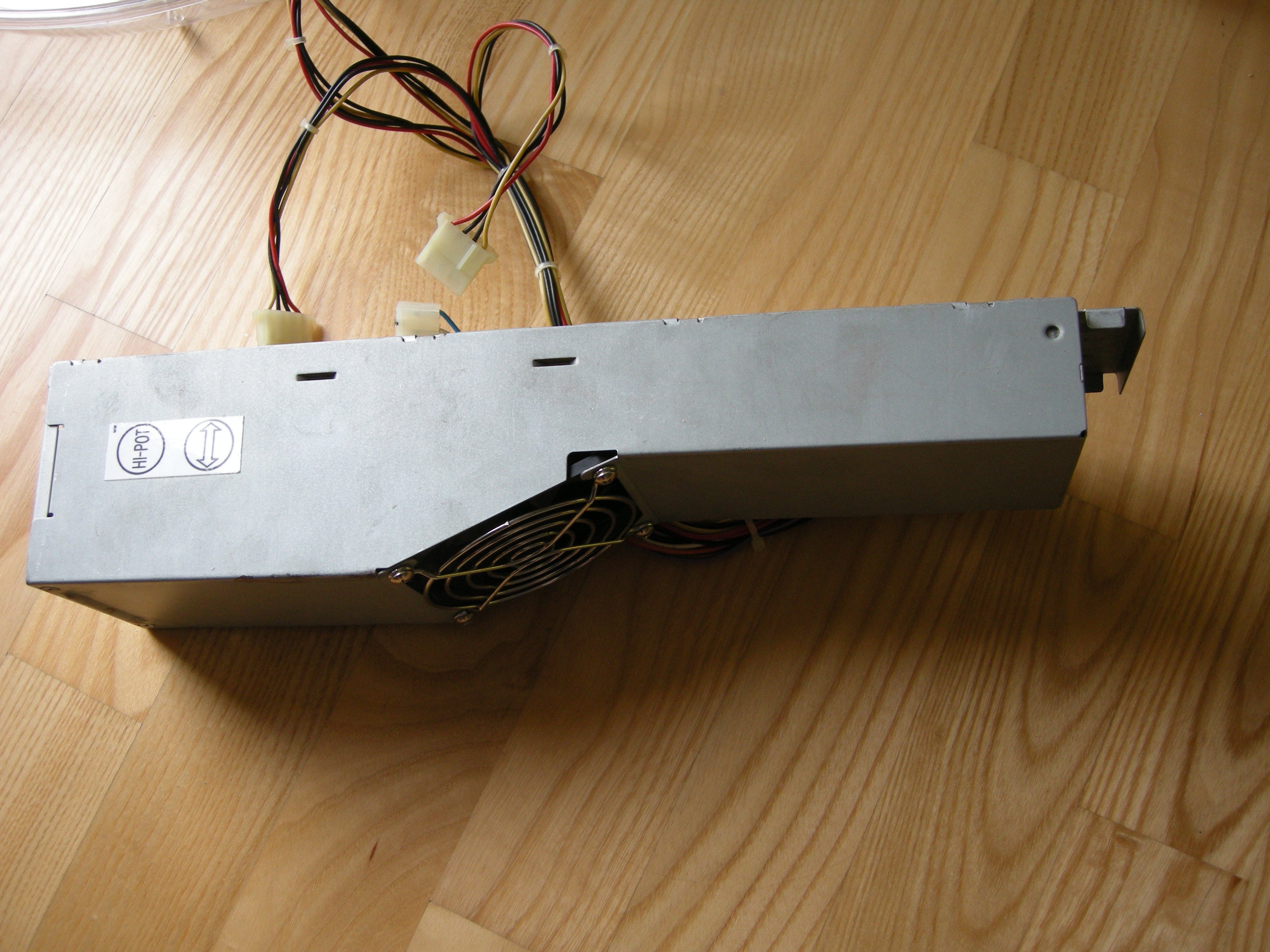
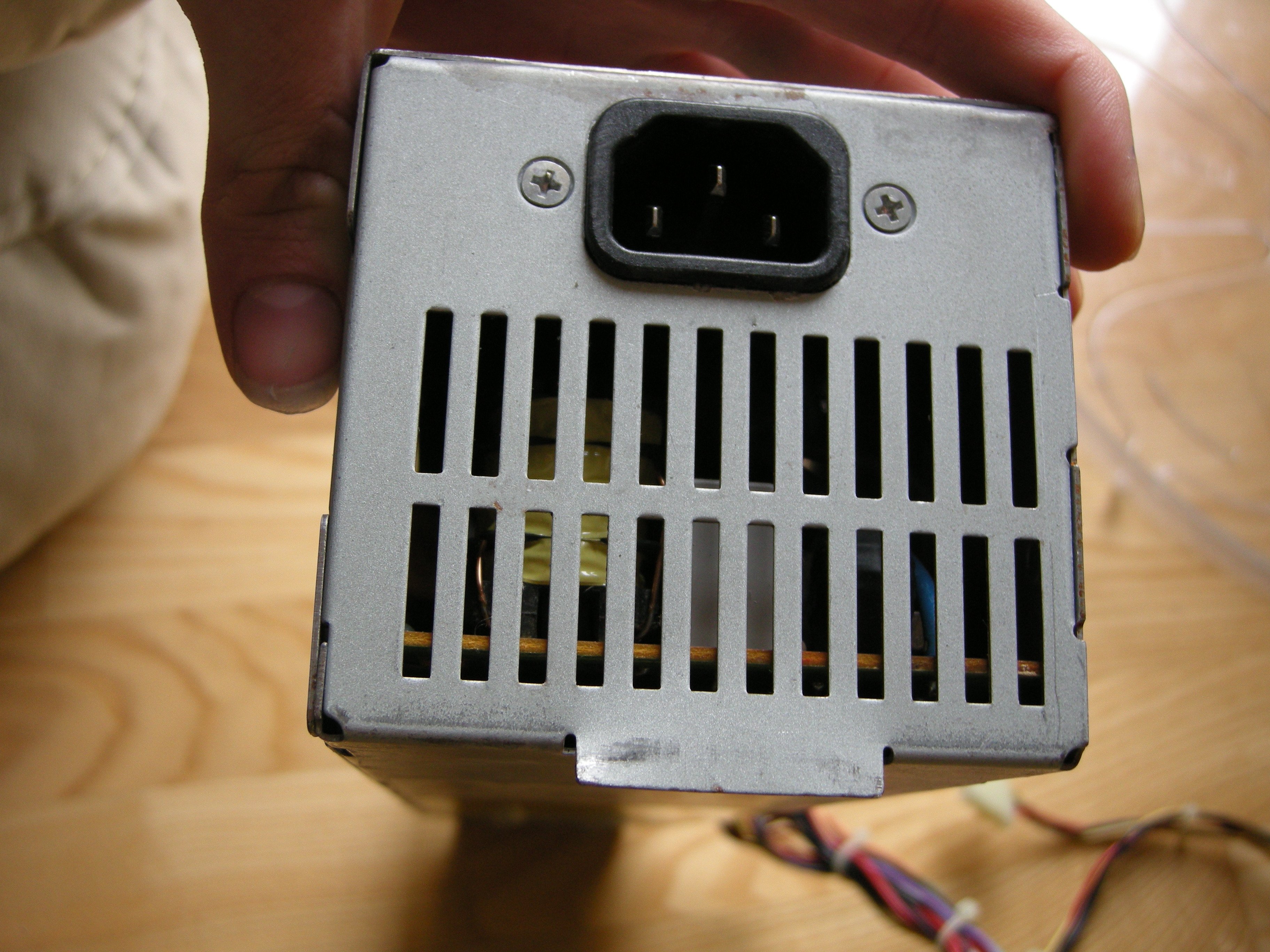
Perhaps the most curious thing about this is the rubber grommet on the molex bundle, which is to say I'm yet to've seen an application which would accommodate it (unsurprising, as this is 5 years older than me).
Hopefully the socket is the standard one and not some abomination!
Replying to @nabijaczleweli
having a very normal 11:29pm
Replying to @nabijaczleweli
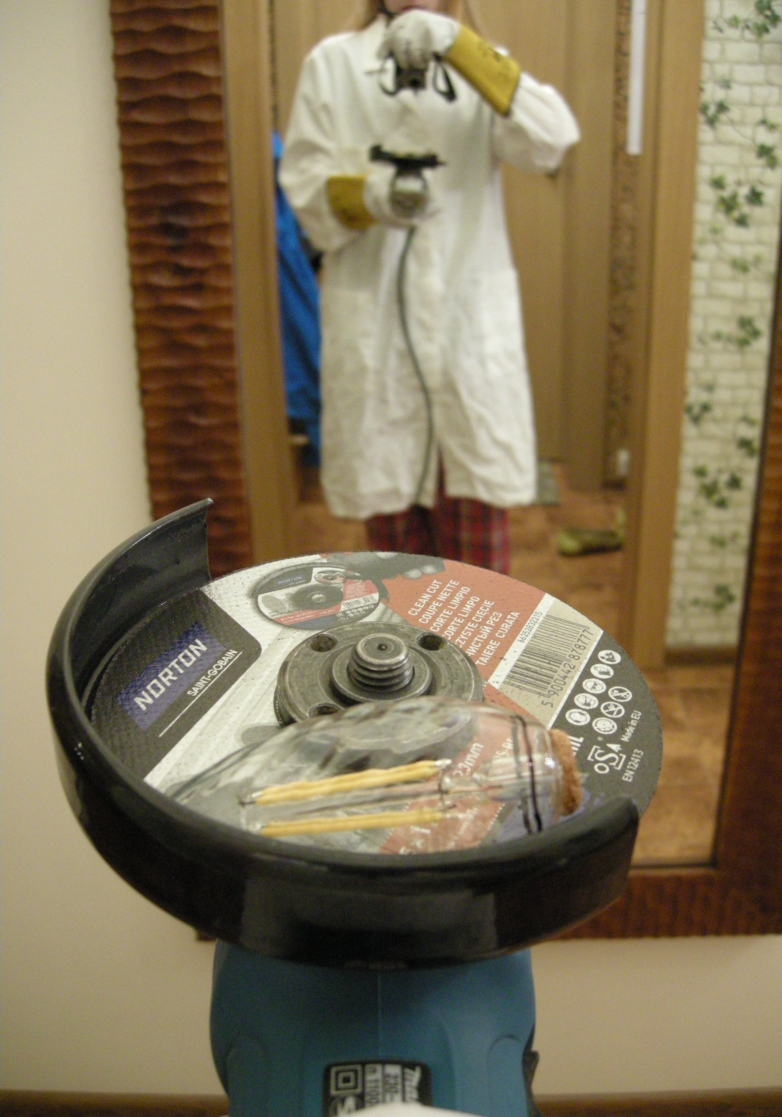
this fucking labcoat still reeks of goddamn sulfur; how long's it been? three god-forsaken months? ho w
Replying to @nabijaczleweli
The Process turned out to be much less clean than I was led to believe, but we've achieved separation with zero deaths, so an overall positive result.
Replying to @nabijaczleweli
The good: I've finally managed to print the AT{,X} connector pinouts.
The bad: it took a good couple hours, printers are cursed, printing software more-so still somehow.
The ugly: this is decidedly *not* an AT PSU, as opposed to what I've previously thought.
Fun!
Replying to @nabijaczleweli
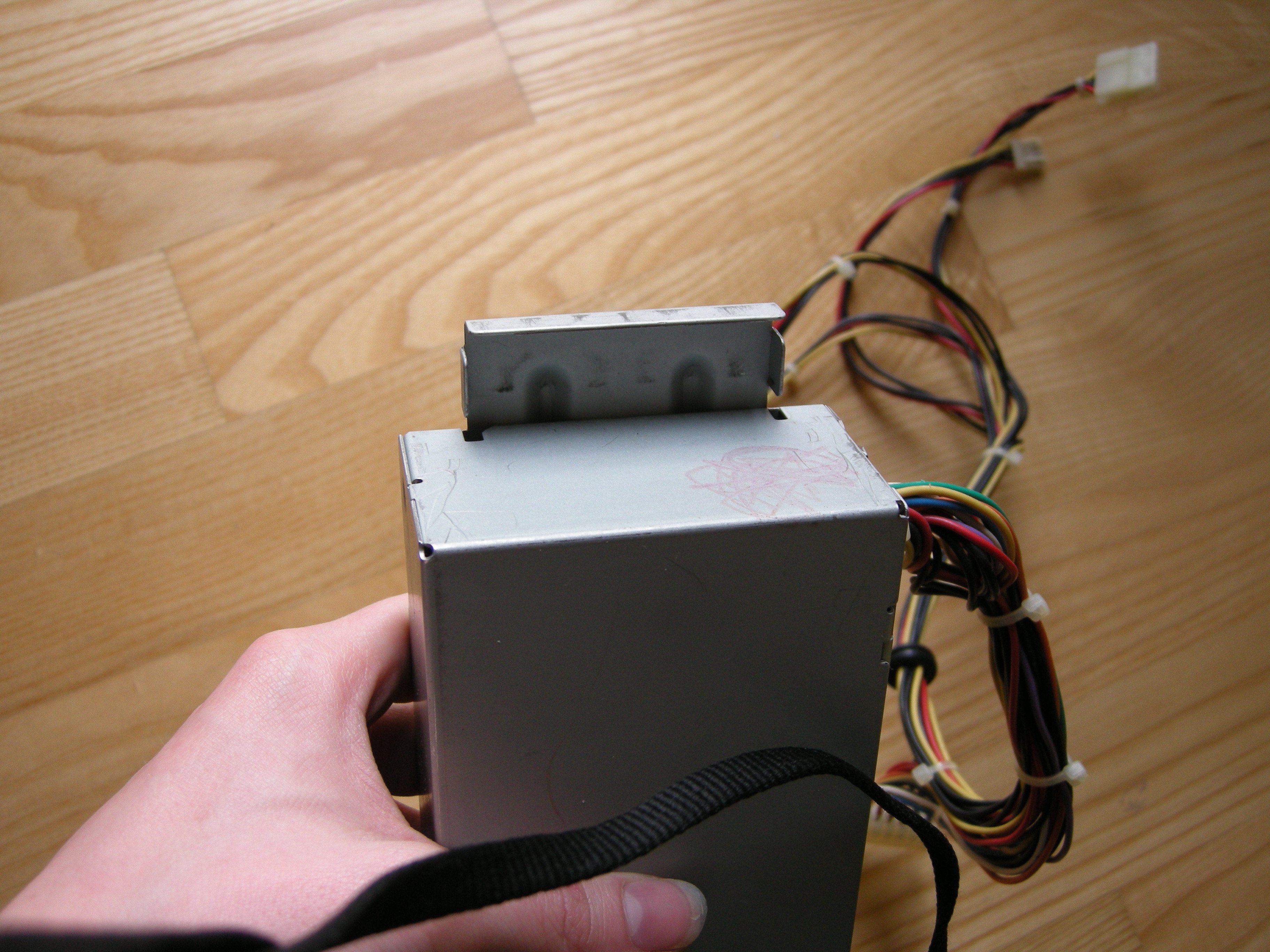
Absolutely *delightful* two-slide axion from the 1mm(!) pressed steel case.
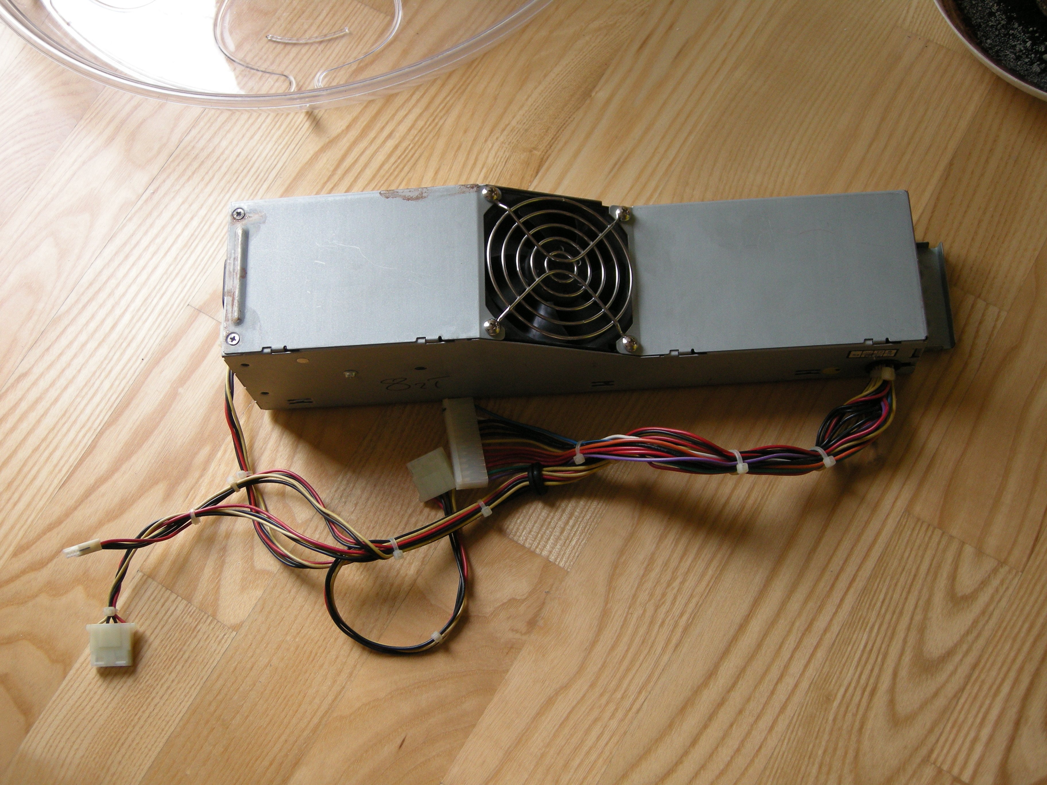
The (retrospectively un)surprisingly-high-quality fan leads are ziptied together.
Similarly, all outgoing cables are crimped before going through the board.
This may sound idiotic, but I feel… unworthy
Replying to @whitequark
eh, we've all been there

The duality of mira


Replying to @nabijaczleweli
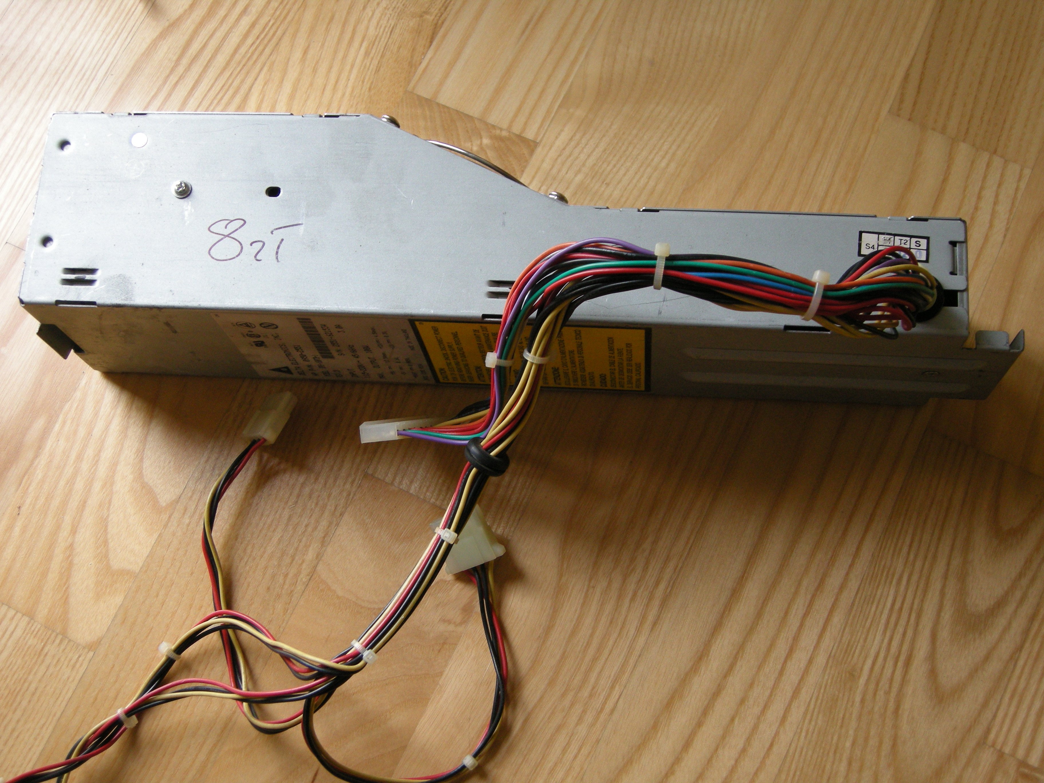
Label says 1995, week 34.
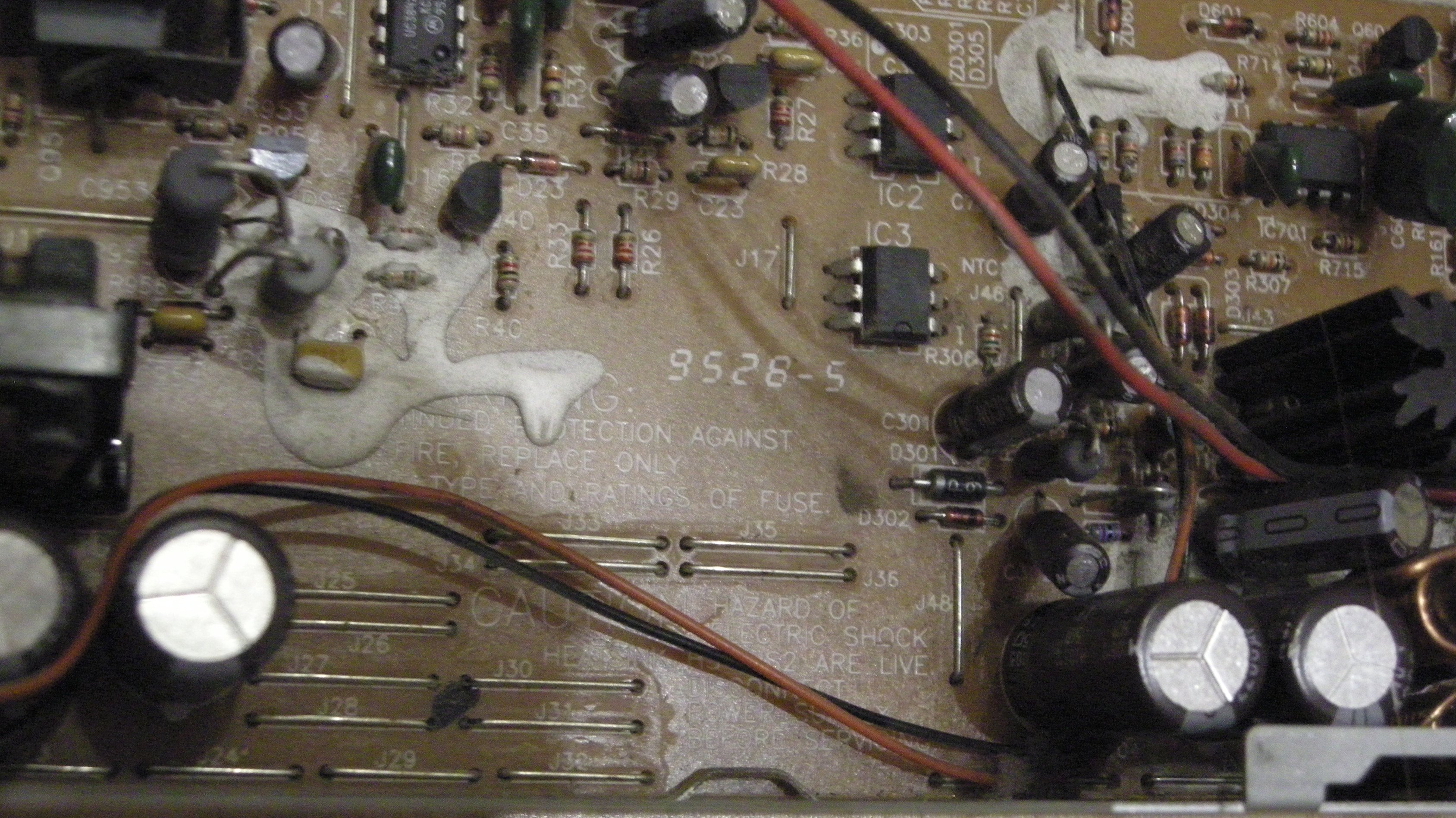
Board says 1995, week 28. And that's already version 5.
That's five and a quarter years older than me.
It's served its function for over twenty four years.
I have not functioned even remotely correctly, ever, over my eighteen years.
i n a d e q u a c y